Iteration 3 overview
Essentially, a charge controller is a high-power switching device. The switching core determines how much energy flows to batteries, and how much excess energy is burned by a dump load. Next picture is key and PMD2 of our system design:

Of course, for our experiments in iteration 3 we needed devices and more specifically, high-power devices. So we ordered two high-power, two-channel switching boards:
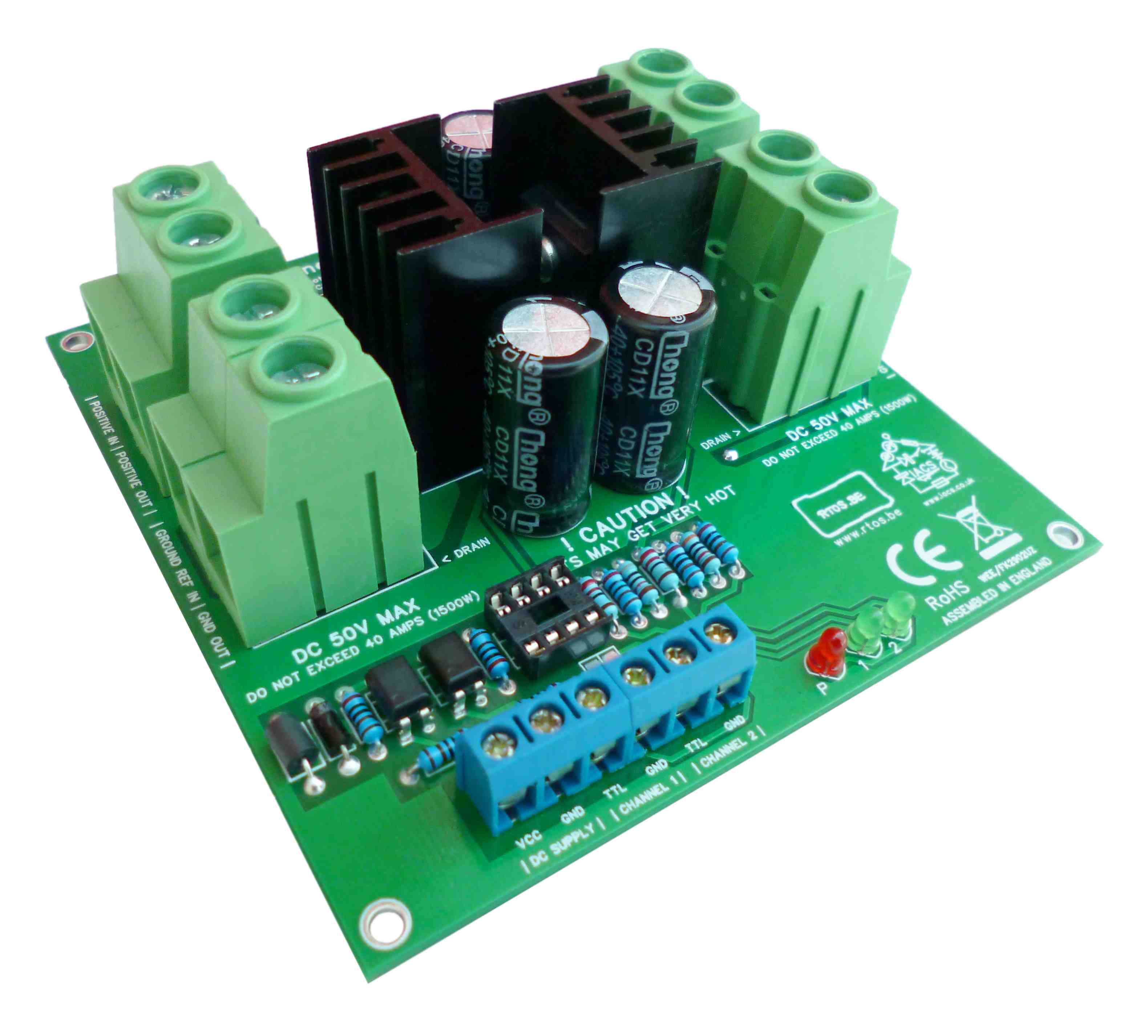
- a low-side switching board, made by IACS. This board will be available for sale shortly. And,
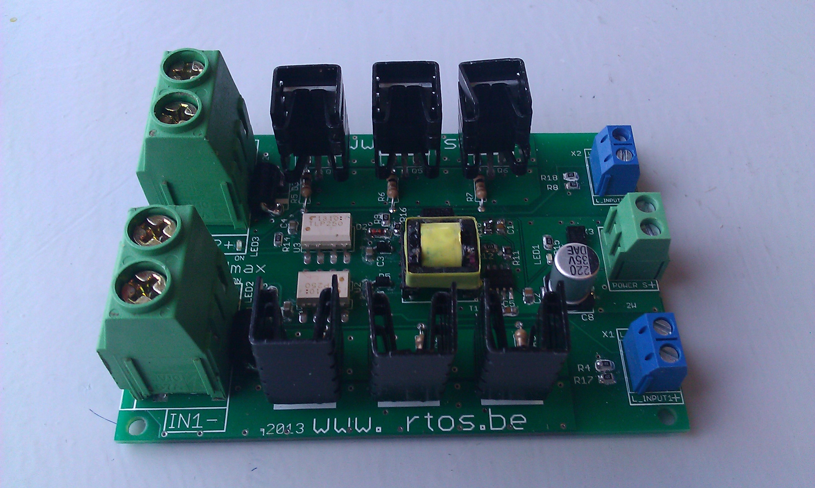
- a high-side board, made via Elance by an Ukrainian engineer but this had to be fixed later on by our local hardware engineer. You can read about our Elance experience here.
We mainly experimented with the low-side switching board that we call ‘energy 2 switch’. We charged a battery ‘the hard way‘ i.e. without a software control algorithm, and tested dual-channel switching with several PWM configurations.
But more exiting, ‘real-world’ stuff was done as well: this article explains how to build a wind-turbine simulator, and of course, how to charge a battery with it. These tests exposed the need for filtering sensor data e.g. with FIR and/or IIR. Sensing volts and amps was done with our own sensor board and with 50V 90A/180A Attopilot devices. For the wind turbine enthusiast, recycling a VAWT as a HAWT is a nice read.

At system level, we investigated several wiring schemes depending on switch/load positioning:
- high-side wiring diagram: loads are ‘above’ switches, all ‘-‘ connected, and
- low-side wiring diagram: load are ‘below’ switches, all ‘+’ connected.
Based on our experiences we probably opt for a low-side switching design.
From the software side we tried STM32 boot (instead of using JTAG for flashing the image) and defined an algorithm for storing and loading of settings (possibly making use of CRC).
After this long iteration of playing with sensors, high-power switches and simulators, we know what we want and we are ready for the real thing in iteration 4.
Iteration 4
Iteration 4 will start with the specification of (the very first version of) our charge controller. The foundation is already defined (our development runs in front of our blog), here is a preview!
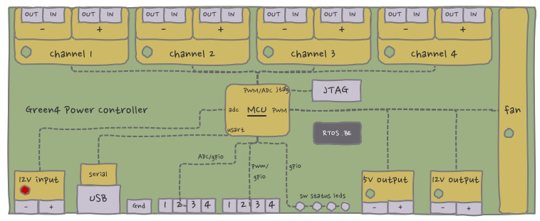
The Green4 Power Controller is actually a generic high-power switching device that can be used to build a charge controller. Development of this device is for our Belgian hardware engineer, and this will probably be our highest (direct) cost.
After hardware development a test phase will follow (and hopefully not too many hw patches) after which we can finally build our charge controller software.
In iteration 5 (probably the last iteration) we will deploy the ‘Green4’ in real-world!

Speak Your Mind