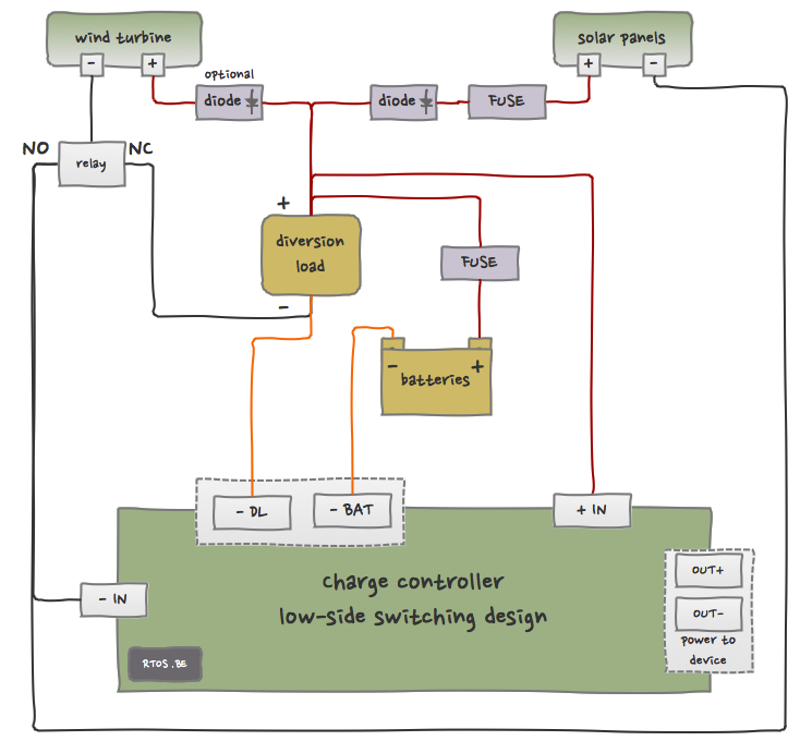
Connection scheme for low-side switching
In comparison to the high-side wiring diagram we saw in part 1, the connections for low-side switching are the other way around:
- all ‘+’-s are connected (instead of all ‘-‘-s), and
- the (power) switching devices are ‘below’ the loads (instead of ‘above’).
In order to better explain this diagram, we need to separate the different functions from each other. These functions are actually the Power Management Decisions (PMDs) we saw in the System Architecture:
- Function 1 (PMD1): wind turbine power to diversion load or to device?
- Function 2 (PMD2): wind/solar power to batteries (or diversion load)?
- Function 3 (PMD3): power to device?
Wind power to diversion load or to charge controller
The state of the relay (NO or NC) determines whether wind power is burned by the diversion load or not. Unfortunately, because all pluses are connected, solar energy might be wasted as well. Because the relay is positioned between the ‘-‘ of the wind turbine and the dump load, we are applying ‘low-side’ switching here.
When the relay is in state NC then power flows from ‘+’ (solar/wind) through the diversion load to wind turbine ‘-‘. This state protects the device against too high power input, and keeps the wind turbine loaded as well.
When the charge controller empowers the relay and its state switches from NC to NO then there is no closed circuit anymore via dump load and relay NC… and power has to go ‘somewhere else’.
Power to batteries or diversion load
When the relay is in NO then the ‘-‘-s of all devices are connected: wind ‘-‘, solar ‘-‘ AND device ‘-IN’, resulting in one ‘big’ mass for all. There are only two paths to get the power from ‘+’ to the mass ([/] denotes a device internal switch):
- ‘+’ -> dump load -> ‘-DL’ [/] ‘-IN’, and
- ‘+’ -> batteries -> ‘-BAT’ [/] ‘-IN’.
It is up to the device internal logic to decide which circuit(s) to open or close, and this is what internal power switching is about. It allows full control of how much energy is pumped into the batteries. As we explained in this article, the optimal charge mode depends on the battery state. The energy harvester will use PWM-driven mosfets to do the power switching (see also here), but this is beyond the scope of this article.
Power to device
The charge controller can use ‘+IN’ to power an external device. We will expand upon this topic later when the charge controller internals are explained.
Fuses and diodes
Fuses protect against overcurrent. If the user connects out-of-spec solar panels then our system is able to ‘disconnect’ from this high-power source. The batteries are protected as well; the last thing we want is a fire in the house…
Diodes guarantee that current can only flow in one direction. Diodes are not ‘free’, they incur a (small) voltage drop. When the wind turbine – maybe based on a DC motor which is now used as a generator – doesn’t have a diode bridge rectifier (or alternative device) then we need to add a diode to avoid wasting battery power in the wind turbine.
In conclusion: drawing low-side wiring diagrams
- Connect all ‘+’-s,
- Place the switching devices (mosfets, relays etc.) between the ‘-‘ and the load,
- Verify that the circuits are correctly closed when the switch is ON/OFF (or the relay is in NO/NC), and finally,
- Add safety devices (fuses) and ensure current can only flow in the ‘correct’ direction.


Speak Your Mind