Prototype building block
While working on our energy harvester design, we have identified a couple of relatively independent building blocks that could also be interesting for other people doing projects and building prototypes. One building block is the switch: In its most basic form, it closes an electrical circuit after which a load can get electrical energy from a power source. Another building block is – for example – the current sensor.
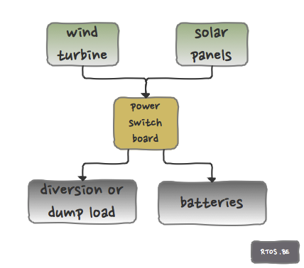
In our particular case, we want to manage the energy flow from our generators (wind and/or solar) towards the loads (the battery-bank and/or the dump load).
But many other DC applications are in need of a fast switching electronic component or module. For example: DC motor management, dimmers in home automation, intelligent battery charge controllers, etc…
So, we started to specify our “energy-to-switch board”. Furthermore, because both options have their specific place in the solution domain, we decided to split the prototype development in 2 parts: One for high-side and one for low-side switching. Of course, our target applications have high power properties.
2 SPST per board
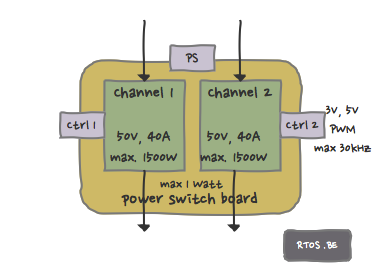
The boards would have 2 independent switching channels, each capable of handling 50V, 40 Amps and handle maximum 1500W of continuous load (e.g. 37V at 40A). Also, if at all possible, it should be passively cooled.
For the high-side board, the concept is that of an SPST relay where both channels do not share a common ground. The low-side switch board does have a common ground and it is that ground connection that is switched.
Both boards are to be used as a module which can be connected to e.g. an arduino (5V logic) or e.g. a STM32 value line discovery board (3V logic). The boards can be seen as a combination of 2 DC relays that can switch fast to “throttle” the amount of power that is passing from IN to OUT. The optimal duty cycle and frequency is dependent on the application, the power supply (IN) and the particular load (OUT).
The power supply to the board should be isolated from the switched power in the relays, and should not exceed 1W.
Frequencies for PWM should be up to 30 kHz because at those higher frequencies the switching is no longer causing troublesome noise for the human ear.
The technology components that execute the switching are of course (power) mosfets. However, mosfets are unidirectional current gatekeepers: they only block current flow in one direction and always allow current in the other direction. Hence, if one wants to control current flow in both directions, the 2 channels can be set back-to-back for bidirectional current control. For battery charge applications, that is an important property. In order to reduce the electrical resistance of the switch, multiple mosfets can be used in parallel. But that depends on the design.
Design solution
One important remark: There is no such thing as a ‘generic general purpose switch solution’, but at least our boards should be a good attempt or starting point, which – with minor modifications – can be adapted to most applications.
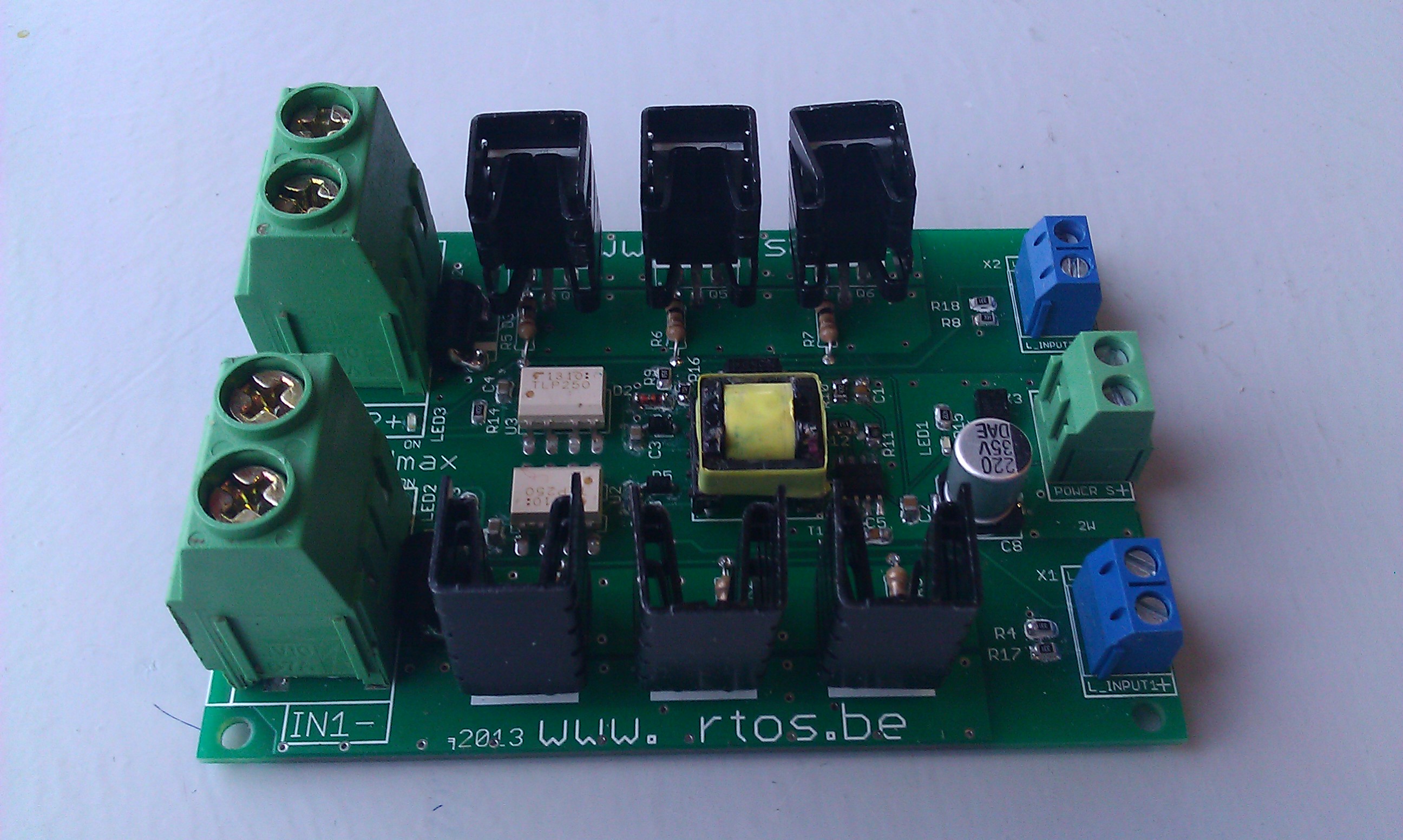
The assignment for the low-side switch board prototype was given to IACS. The high-side switch board was developed by an independent electronics freelancer and supervised and reviewed by us and our local HW engineer. Both boards are currently undergoing harsh tests to determine the final specifications. A sneak peek of the high-side switch prototype board is depicted below.
Both boards are to be commercialized, so if you are interested drop us an email.

Speak Your Mind