Although, there is no such thing as a general purpose mosfet switch board because of the wide variations in application specific load (resistive, capacitive, inductive or mixed) characteristics, we were able to investigate and demonstrate DC motor control with our prototype board.
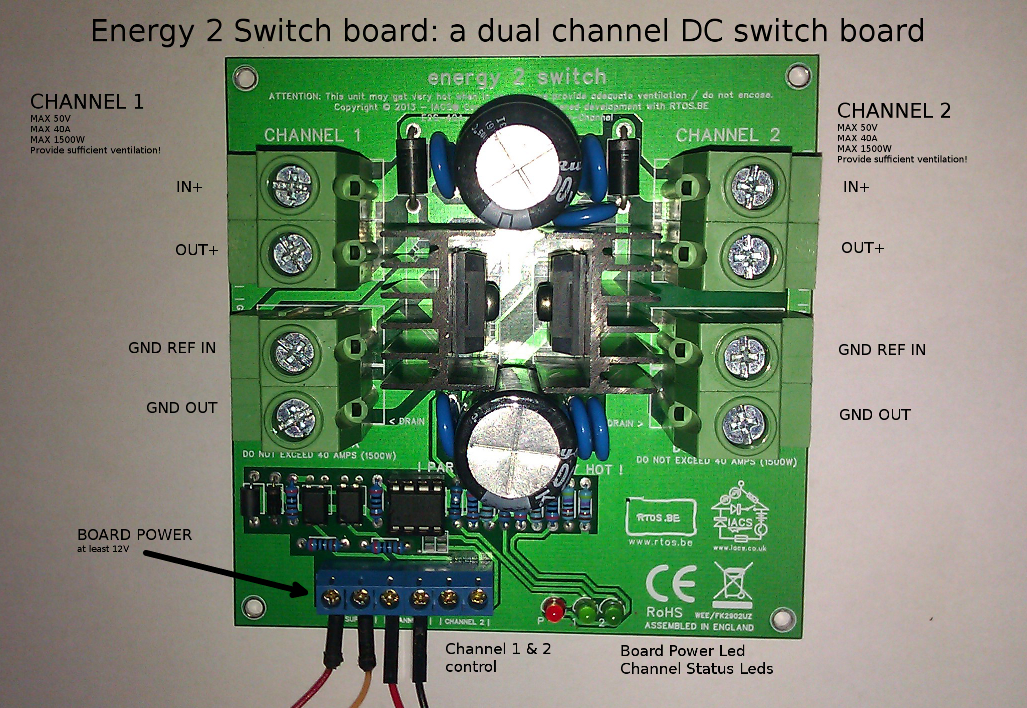
 Then, we performed the same tests on the energy2switch board.
The brushed DC motors used under test were a 24V 350W variant and a 48V 750W (1HP) version. Speed control was performed with PWM. No braking or reverse direction (the board is not a H-bridge), but only drive and coast are possible. A running DC motor is a rather special load that can become a generator when no longer supplying power to it. Also during start-up or acceleration conditions, the DC motor can draw a lot more current than in normal run mode: “Across-the line starting of induction motors is accompanied by inrush currents up to 7 times higher than running current, and starting torque up to 3 times higher than running torque.” Soft-start features or controlled duty-cycle change rates are essential to limit the current draw.
Soft-start
A Soft-start implementation for PWM is simply a matter of having a duty cycle change rate algorithm. If the current duty cycle is 0, and the requested duty cycle is 100, the algorithm will change the duty cycle from 0 to 100 in steps. The system is an open-loop control system if there is no feedback with regard to the current. This can work if one can tune and test the system under the different work conditions.
Current limiting
If however, we do use the information from a current (and voltage) sensor to adapt the step rate or even the attained duty cycle, we have a closed-loop control system. This was implemented in our controller software for the STM32 value line evaluation board. If the sensed current exceeds the set arbitrary limit, the effective duty cycle will decrease (at the maximum of the change rate) until the current is again within the aforementioned limit. The implemented current limiter is rather coarse and linear but it works well. It would be possible to implement a PI(D) controller for the problem, but that was – in this simple case – not really necessary.
Soft-stop
The same principle – except for the current limiting – applies for requested duty cycle decreases. Power is removed from the DC motor in steps, avoiding sudden generated surges from the DC motor, now generator.
PWM frequency
The frequency we currently use on our prototype boards is maximum 250 Hz. This is not ideal for motor control since it can produce audible noise: One can hear the PWM frequency. The idea is to improve the board in the following revisions to increase this frequency (preferably to +30KHz).

Speak Your Mind