We are pleased to announce the creation of our very first hardware component: the PMD1 sensor board. We won’t let you wait, here is a beautiful image:
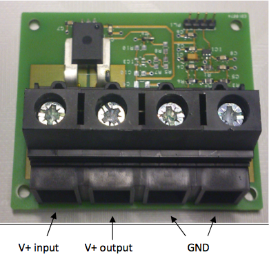
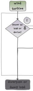 Now, let us start with the global picture. The sensor board is part of Power Management Decision 1 (see Figure on the right). PMD1 decides whether the power from the wind turbine (V+ input on the top picture) can be accepted by the charge controller (which is specified to a maximum of 1500W) or must be diverted to a load (e.g. a dump load).
In order to make this decision the software on the MCU has to know the incoming wind power, and this is where the sensor board comes into play. The sensor board provides the MCU two linearly scaled analog voltages which represent:
- the current and
- the voltage generated by the wind turbine.
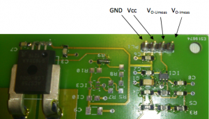
Both analog voltages are delivered via the Vo-Umeas and Vo-Imeas pins (and can be measured by the MCU via the ADC peripheral).
The U-measurement has a span of 0 .. 4V where 0V ~ 0V input, and where 4V ~ 100V input, or Vo-Umeas = Vinput / 25.
A current increase of 1A gives a output voltage increase of 40mV (typical). This gives the following output voltage: 0A ~ 600mV and 100A ~ 100A * 40mV + 600mV = 4,6V, or Vo-Imeas = 0.6V + Ainput*0.04V/A.
Some other specifications
The board:
- works between 3.3V and 5V (but best resolution at 5V).
- is able to resist peaks of 100A and 100V (why?).
- should be EMC compliant (this is not tested though).
Notice the big 25mm2 connectors. Given the above spec’s, this is theoretically correct (AWG-4) but an overkill for practical applications as no one is going to pay for 25mm2 copper wiring. Probably 15mm2, 10mm2 or even 6mm2 will do in the real world. What is your experience?
Testing the device
Work is never done without a real test. Here are a picture of the setup:
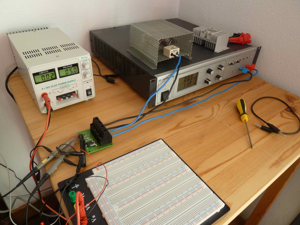
The output is according to the spec. On the scope we saw some strange ‘artifacts’ in the measurements. After some investigation we found this was the real output of our heavy power supply (the wind simulator), probably due to current limitation.
Power consumption was 20mA @ 5V.
Hardware schematics
The input voltage is scaled to the 0-3.3V range by a voltage divider while a linear Hall-effect based sensor (ACS758) is used to measure input current.
The internal circuitry is protected against overvoltage by the well-known ‘blue disk’ which is a 100V varistor.
The schematics can be downloaded here.


Speak Your Mind