In order to charge batteries with the wind turbine simulator, the setup already becomes quite elaborate.
First, there is the brushed DC motor which drives the axial flux turbine. It has a 24V, 350W and maximum 19A rating.
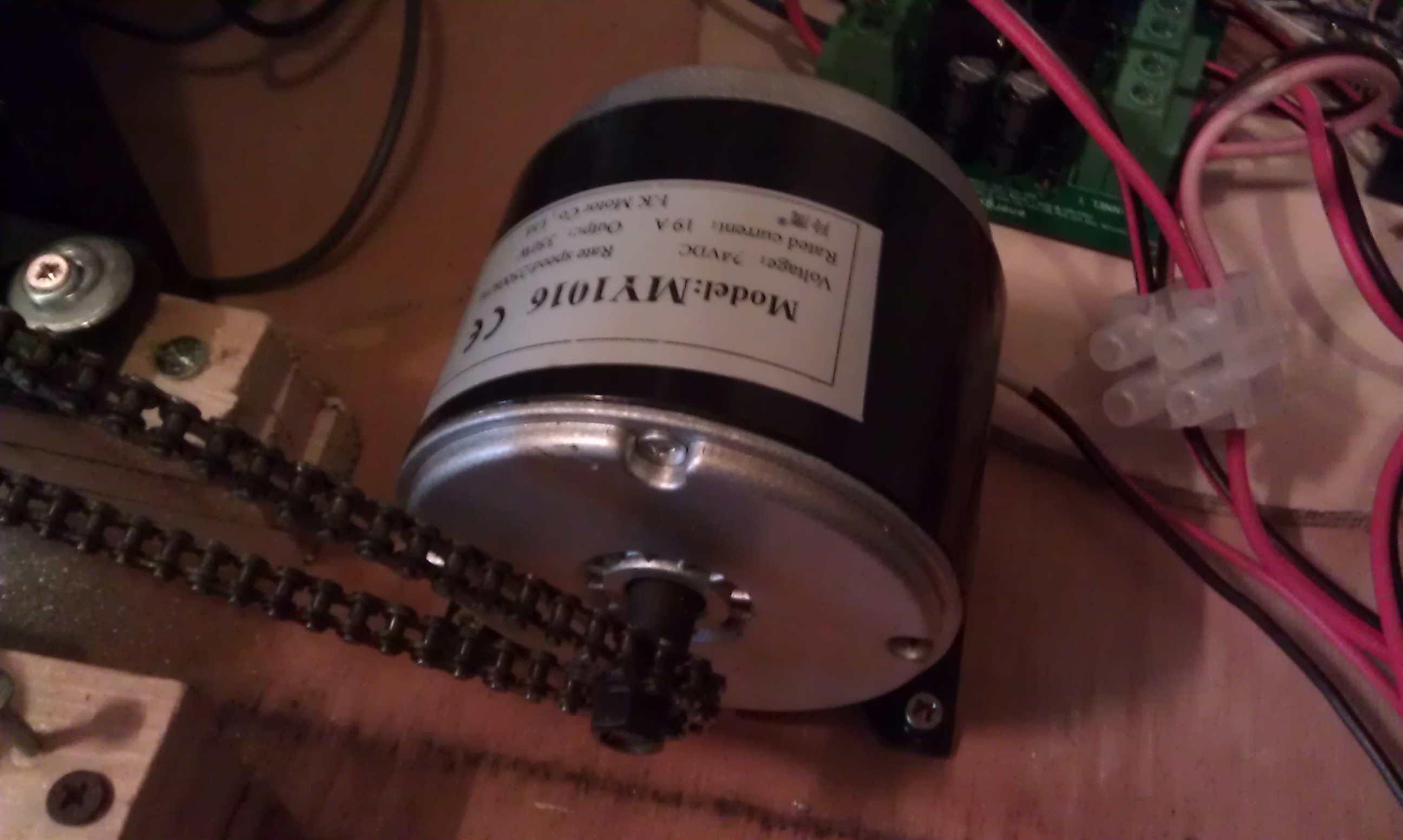 The DC motor drives the generator with a chain gear to step down the high RPM of the motor to a lower input RPM for the generator. It should go from maximum 2500RPM to about maximum 600RPM. Note, that we never tried to actually achieve 600RPM on the generator since the entire contraption is not that solid and there is too much vibration with higher RPM.
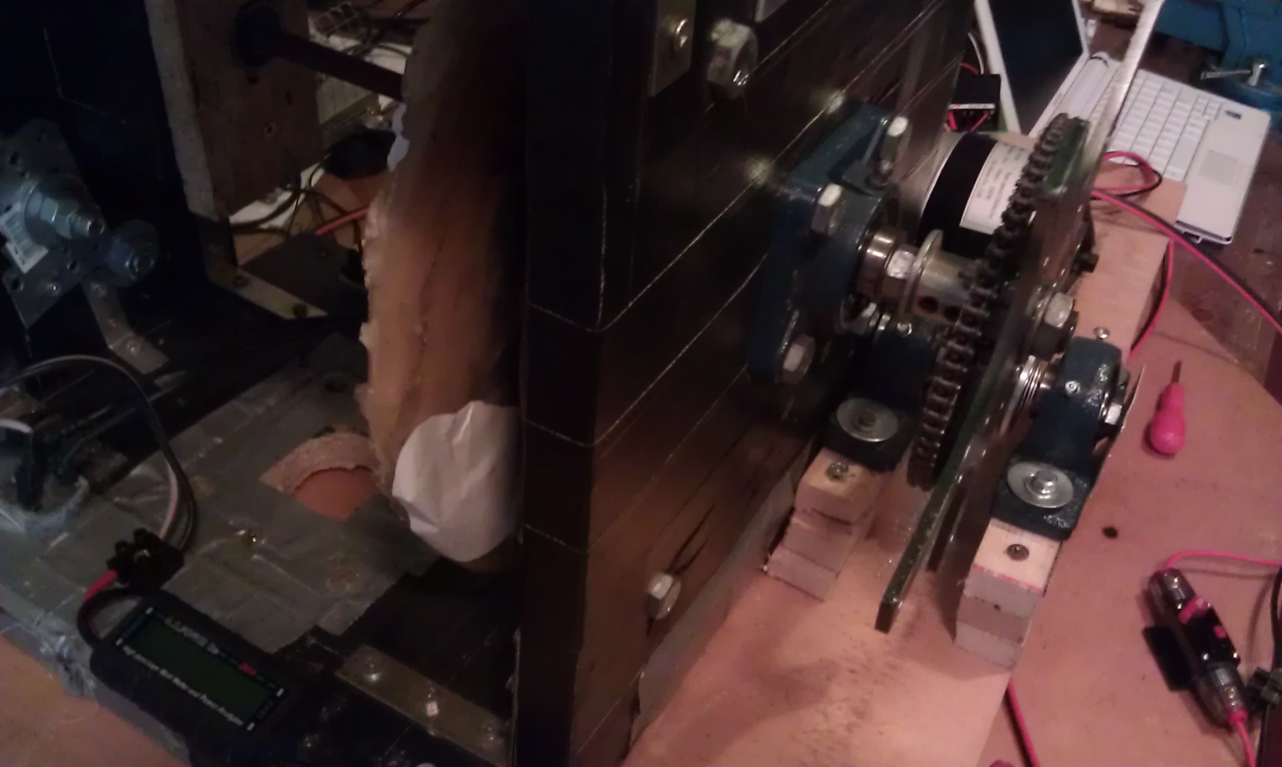
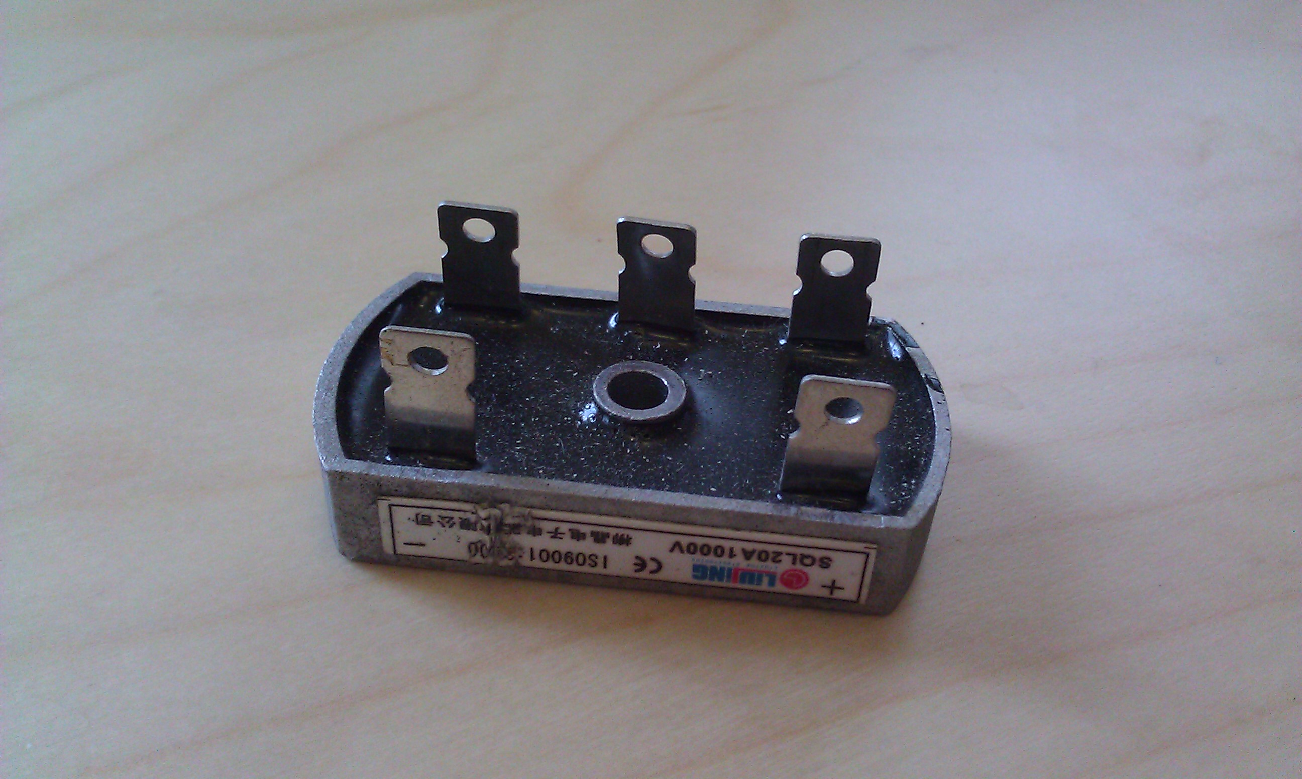
Also, the open voltage on this generator rises quickly under higher RPM; at the time, the stator was built for 24V battery charging. The Alternating Current this generator produces is converted in Direct Current by a full bridge rectifier.
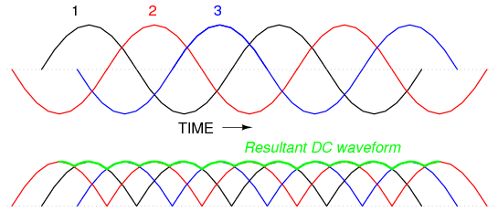
 Below, one can see a representation of the 3 phases of the AC out of the generator, and the resulting DC. That is a theoretical image, in reality it will look much uglier and have more ripples.
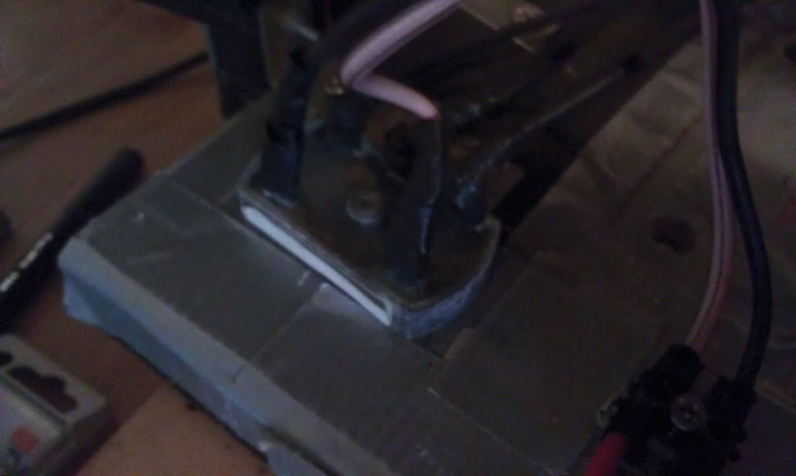
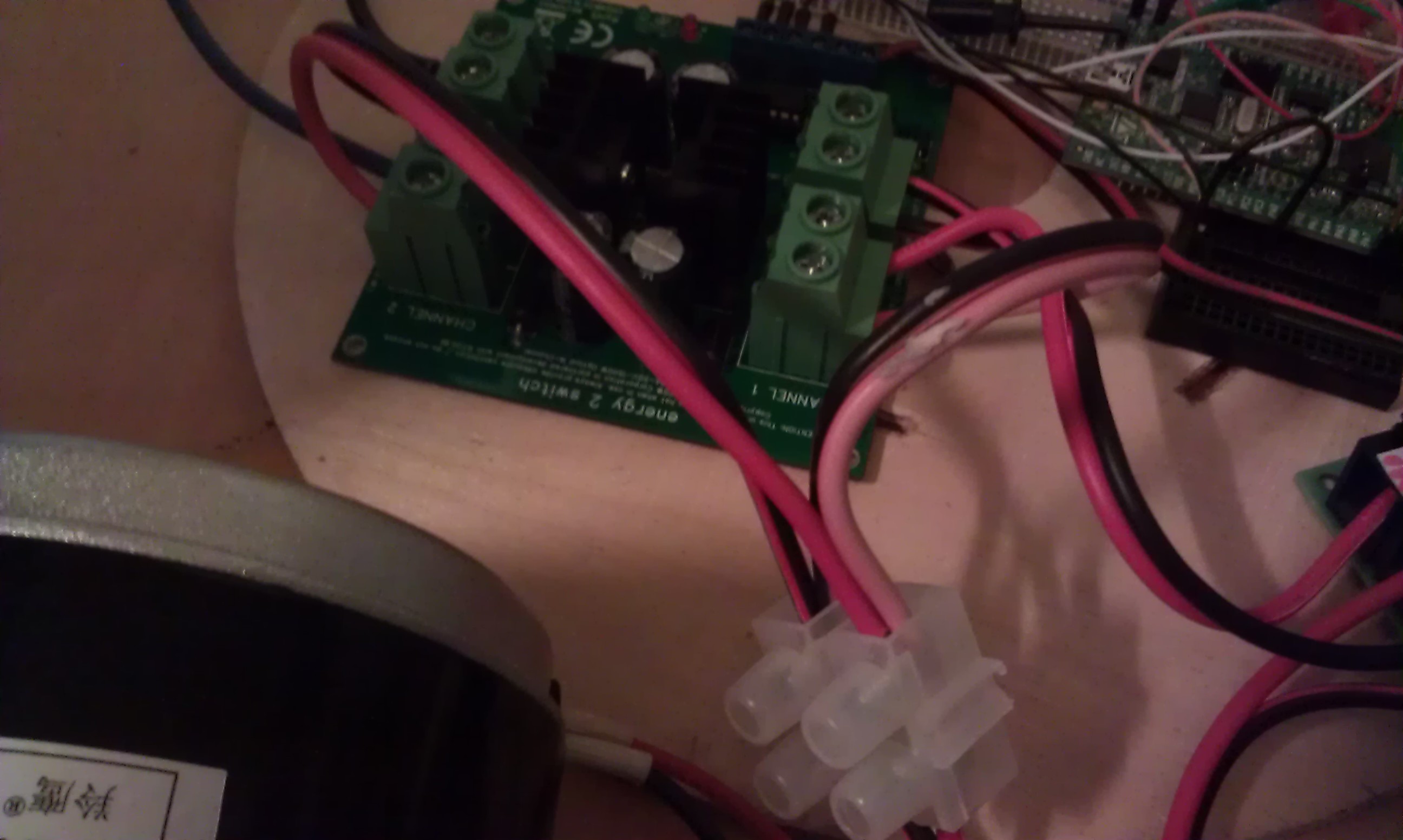
This raw-and-rippling Direct Current, is – in this setup – fed into IACS low side switching board on BOTH channels. The output of channel 2 is connected to the dump load, and the output of channel 1 is connected to the battery-bank. The 2-channel low-side (mosfet) switching board is controlled by our application running on the stm32 value line evaluation board as can be seen on the right side of the picture below. In the middle of the photo, one can see the mosfet switch board.
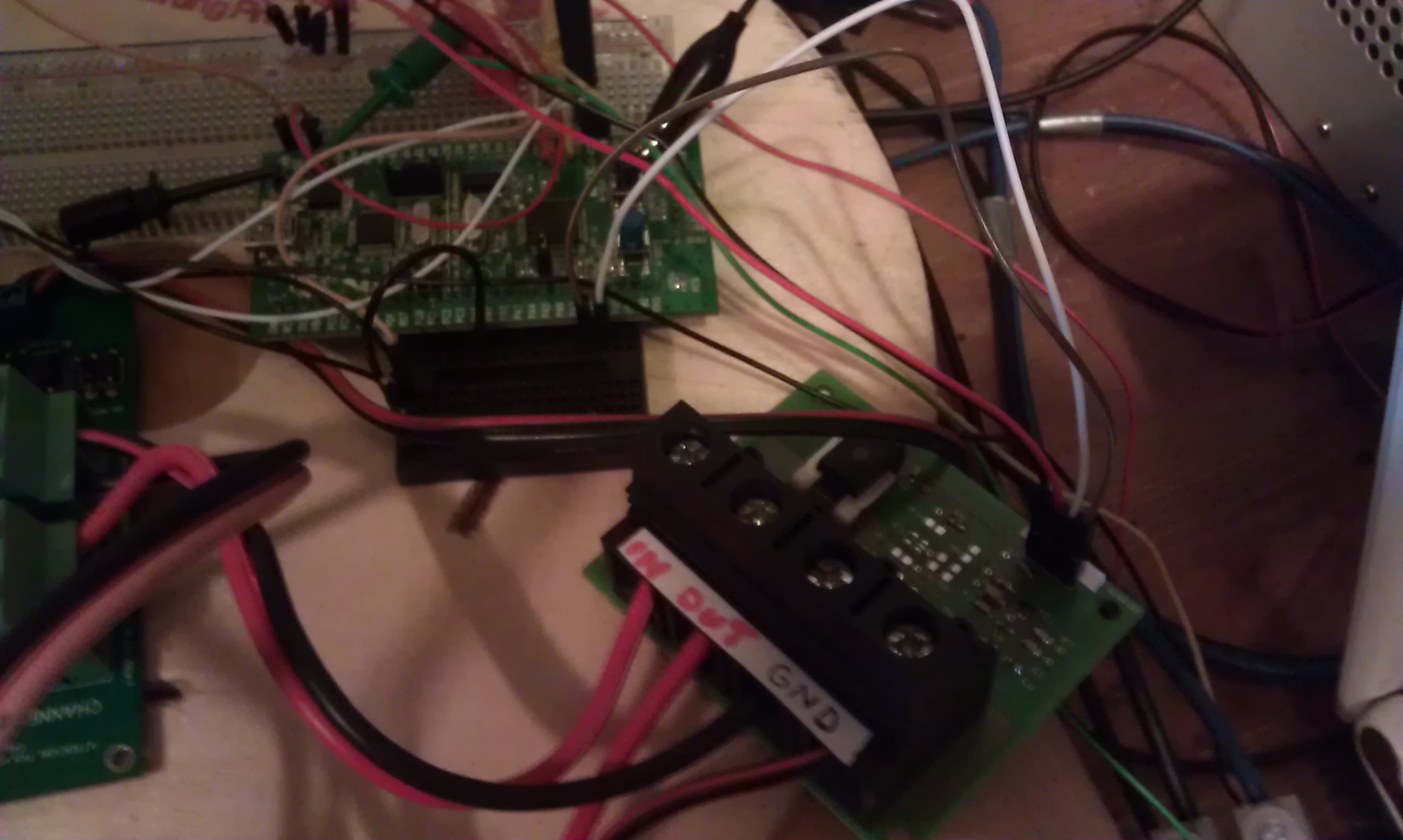
 The amperage towards the battery-bank and the voltage of these batteries is being ‘sensed’ by our PMD1 sensor board. In this particular setup, the current and voltage sensor board resides between the output of channel 1 and the batteries. Infinite Impulse Response and moving average (which is a Finite Impulse Response) filters implemented in software had to be used to get stable and reliable voltage and current readings when using PWM.
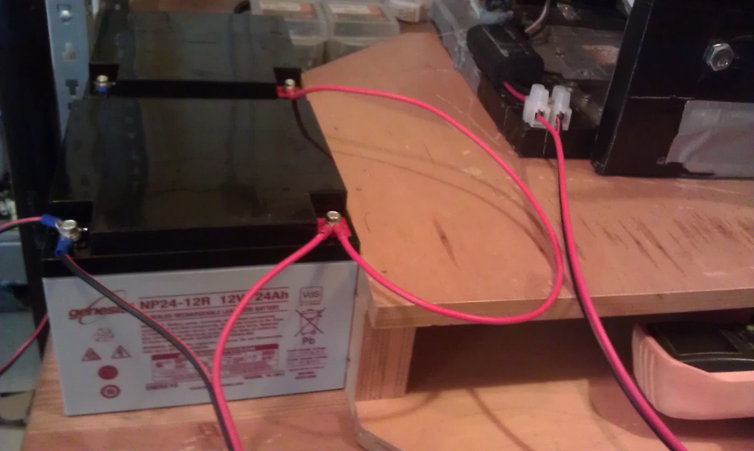
 This battery-bank consists of 2 smaller 12V 24Ah deep cycle batteries wired in parallel to provide sufficient back pressure to the generator. I picked smaller batteries for this simulator setup because they are easier to handle: Try lifting a 200Ah battery and you will know what I mean. Normally, there should also be a fuse between the positive connectors of both batteries, but this was omitted in the test setup. There IS a fuse between the positive terminal of the battery bank (and the sensor) and the mosfet board.
Mosfets offer only single direction control (block or pass) for electrical current, current in the other direction is always allowed to pass (unless there is an extra diode preventing this). Hence, the current from the battery can flow back ‘upwards’ channel 1 towards the generator AND channel 2.
But for the axial flux generator, this current is blocked by the bridge rectifier. For channel 2 – which is connected to the dump load – this is (PWM) controlled by the channel 2 power mosfet that can block current in this direction. If we want, we can connect the battery to the dump load when opening up “valve 2” (iow mosfet channel 2; energy now flows from generator AND battery-bank to the dump load). In this mode, the system acts as a standard diversion load controller. For example, when the battery is fully charged and can no longer efficiently absorb wind-turbine generated energy OR the generated energy is too high for the battery-bank to handle, this diversion switch can be activated. However, since we can do PWM on both mosfet channels, we are able to do both: charge and divert, not at the same time but switching between them many many times per second. Moreover, we can attempt to logically separate “controlling the wind-turbine” and “charging the batteries”. More on that later.
The prototype embedded software currently entails
- current limiting: e.g. one wants to set a limit on the maximum average current a battery can absorb.
- soft start: suddenly changing the PWM duty cycle can be deadly e.g. in case of motor control. A DC motor can easily draw more than 10 times its rated current during start-up.
- battery charge profiles: for bulk, absorb and float battery charging stages.
- measuring voltage and current

Speak Your Mind