Introduction
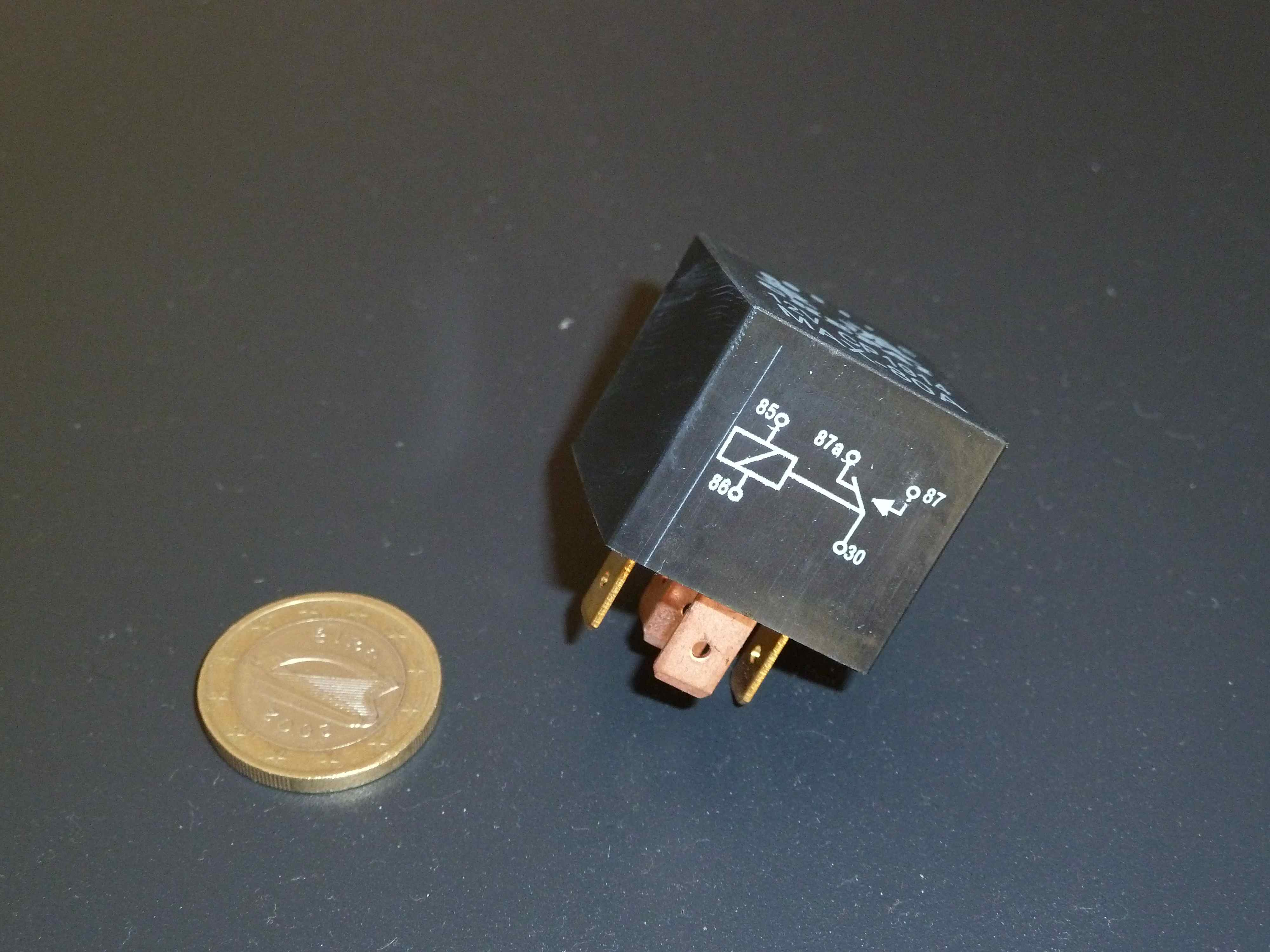
A relay – in this context – is an electronic switch and can be controlled by micro-controller logic. There are different types of relays, with different pin configurations. A 4-pin relay can be OFF (not conducting current) or ON (conducting current): 2 pins are powering and thus controlling the relay and the other 2 pins are then disconnected (open, off) or connected (closed, on). Another configuration is a 5-pin relay which has an Normally Open (NO) and Normally Closed (NC) contact (the fifth additional pin is common to the 2 connections), which means that the NC connection is conducting current when the relay is OFF (then the NO contact is not conducting), and it also means that for the ON state of the relay the situation is vice versa. The photograph shows one of our 80A 5-pins automotive relays with schematic.
The relay boards or kits we find plenty-full available in the market can – for example – be selected on
- number of relays,
- the coil voltage of the relay,
- the logic voltage level or TTL which determines the ON or OFF state,
- the power usage of the relay,
- the voltage it can switch,
- the maximum current it can handle (which can be different for NO and NC contacts).
Our relay kit (solder not included!)
The kit we experimented with is a single SPDT (5-pin) – Single Pole Double Throw (and also a SPST (4-pin) – Single Pole Single Throw version) relay that was purchased from ebay just to do some quick experimentation on how to use a relay connected to our selected prototype board.
Since we have a 3V TTL level for our micro-controller, the 3V operation version was ordered:
http://shop.ciseco.co.uk/kit-relay-board-simple-to-use-3v-operation-supports-logic-level-also
We can switch 10A at 24V DC with this little relay (but probably not with the PCB :)).
Unfortunately, that particular version has a relay where the coil voltage is 12V, which is fine but maybe it is more practical to have another coil voltage depending on the application…
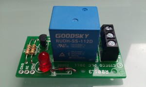
Front top view
This particular relay is a SPDT (5-pin) relay. To control the relay, we observe 3 inputs at the bottom left: GND (common ground or ‘-‘ if you wish), IN (the TTL input which control the ON/OFF state of the relay) and PWR (powering the coil of the relay). The “-” of both IN and PWR must be connected to common GND. IN is then +3V, while PWR is +12V in this case.
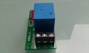
Side view
Above, we also see a terminal with 3 contact points: A1 is the NO, COM is the common input, A2 is the NC.
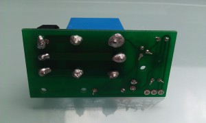
Bottom view
Please note the fantastic it-just-works soldering, which proofs that even embedded software engineers can be creative with hot iron and (lots of) tin. Hey, at least there are no unintended holes in the PCB.
A 3V relay coil voltage would have been nicer because maybe it can then be completely powered and controlled from the Olimexino STM32 without need for a 12V battery or another power supply and more importantly keep the board separated from the 12V battery.
Connections
To summarize, the depicted version has the following connections:
- COM = positive (+) power input
- A1 = NO Output (conducts when relay is ON)
- A2 = NC Output (conducts when relay is OFF)
- GND = common ground (-)
- PWR = 12V coil voltage (+)
- IN = logical 3.3V input (~0V = OFF, ~3.3V = ON)
Switching inductive loads
Switching high current inductive loads, as intended by our application, is hard. Breaking (opening, going to the OFF state) the connection often implies a sharp transient rise in voltage that can damage the involved electronics. There is also the potential harmful manifestation of arcing on the contacts and electromagnetic pulses that can interfere with other circuits and even other devices.
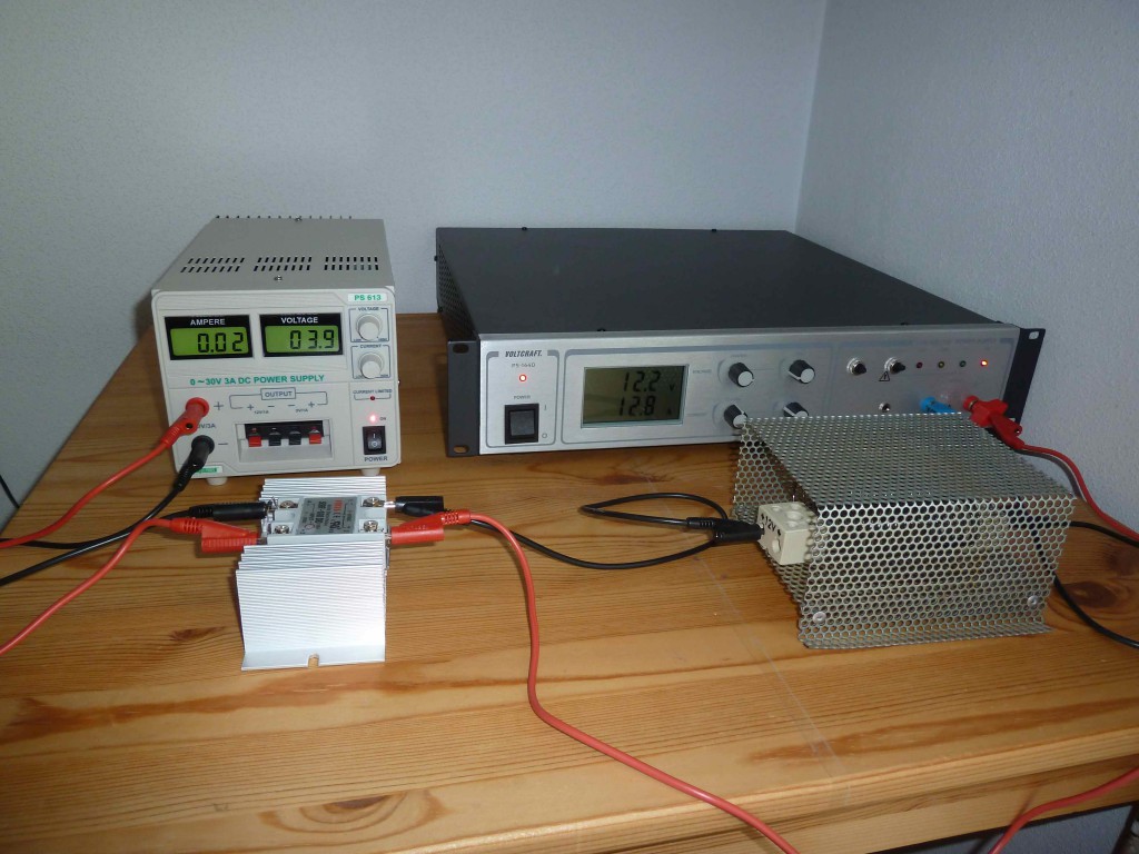
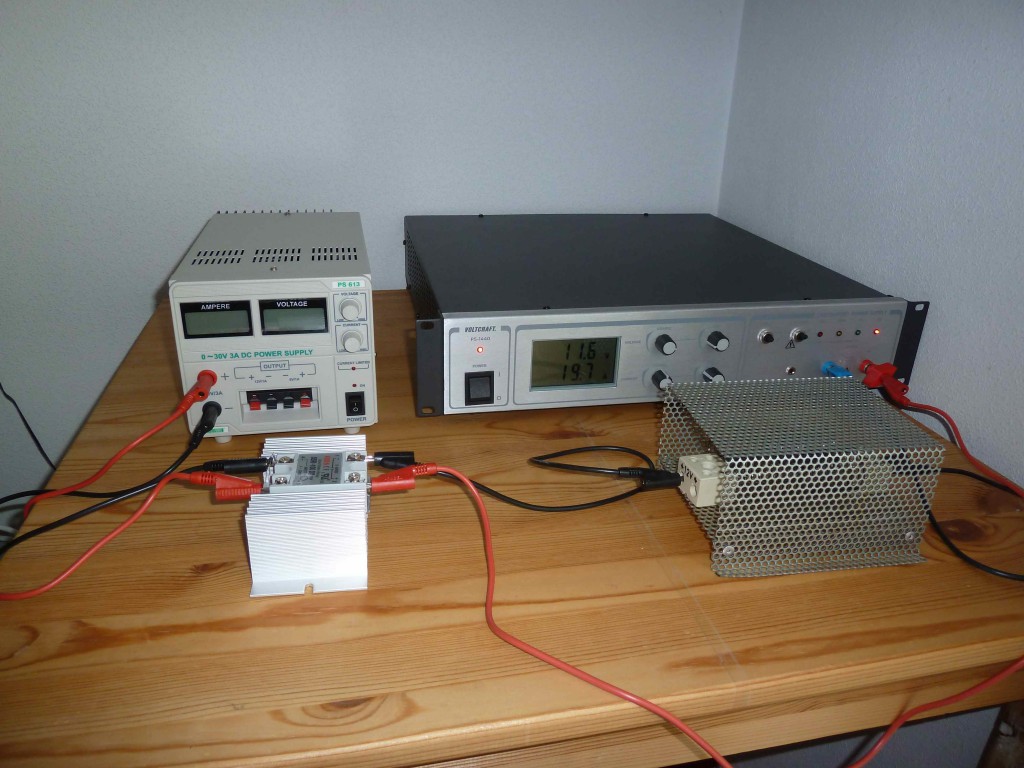
The aforementioned issue is illustrated by next experiment. In the first picture a small 4V DC power supply switches a 100A solid state relay which then conducts a way more heavy DC load. You can’t hear it but the relay was actually making some ‘funny’ noices… The second picture illustrates how hard it is to break the connection: the relay is still conducting although the 4V power supply is turned off.
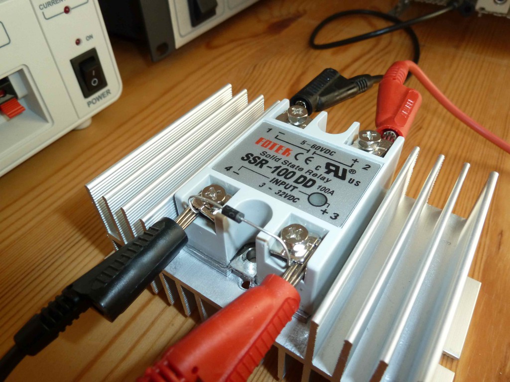
Next picture shows the little protection diode (type 1N4007) to let the voltage die away when the power is turned off. In this particular case the protection diode is not really required.
Switching Alternating Current is easier because at some point zero current will flow through the contacts making that the ideal time to disconnect. Since with Direct Current there is no such convenient time to perform the switch, other measures need to be taken to make it possible to safely switch on and off.

Speak Your Mind