Introduction

After exploring the relay solution space (read part1, part2 and part3), we decided to actually change the boundary of the system and move the relay outside of the energy harvester. Main reason is flexibility and scalability: one could choose a more optimal relay in terms of cost and power spec depending on the (maximum) power output of the wind turbine. Also, one can just leave the external relay out on 2 conditions: No wind turbine is going to be used, or the maximum power of the wind turbine will always be within the power range the energy harvester can handle. Having external relays can also be found in other charge controller architectures see e.g. here.
After doing a scope change it is always an appropriate time to reconsider and take a high-level, ‘black-box’ view on the system again. And now our focus is on how to wire the charge controller i.e. the connection schemes. As we will find out, this actually depends on the internal charge controller design, more specifically the high-power switching between diversion load and battery bank.
High-side and low-side switching
Our goal now is to create two connection schematics: one of high-side switching and one for low-side switching (switching involves external relay switching and internal power switching). Without going into details (this content will find its place in later articles) high-side means the switching device is between solar-wind device and the load, while low-side means the switching device is between the load and the mass. Both high-side and low-side have their advantages and disadvantages, you can read this article for more info. As for now, we just postpone this design decision and define two different wiring diagrams which can be used for prototyping our device internal power switching.

Connection scheme for high-side switching
High-side switching is probably a little more intuitive than low-side switching, at least for software engineers. In order to better understand the diagram, we applied the following coloring scheme on the wires:
- a red wire connects wind/solar ‘+’ to a charge controller internal high-side switch,
- an orange wire connects a high-side switch to a load (battery or dump diversion load), and
- a black wire connects a load with ‘-‘.
The relay switches between the dump load and the charge controller. It is a high-side switch since the load is ‘below’ the relay. The charge controller itself switches between the two available loads which are the batteries and (again) the diversion load. All ‘-‘ are connected to each other which is logical as we are switching on the high-side. Diodes are added e.g. to avoid that our batteries are ‘powering’ the wind turbine (when there’s e.g. no bridge rectifier in place) or the solar panels.
The diagram also includes some fuses for battery safety (we don’t want a fire) and to protect charge controller internals against overspec’d solar panels.
The dashed line is relay control (the relay itself is pushed out of our system spec).
For our current logic design, +WT and +SP could be reduced to just one input +IN.
Also, the -OUT is (internally or externally) connected to the -IN.
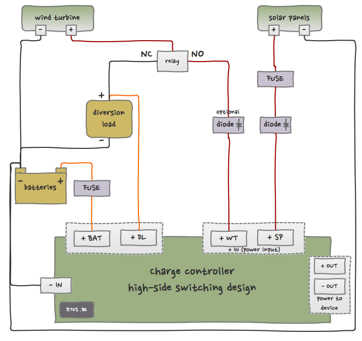
high-side charge controller wiring diagram
In Part 2 we will make the wiring diagram for low-side switching.

Recent Comments