In part 1, we talked about the ‘contactor’. Relays also use power, and in this particular case, the relay coil could draw up to 2 watts according to its specification. In order to save power, there are a couple of things we can do. Using PWM is one of them.
Every relay coil has a minimum operating, a release and a hold voltage.
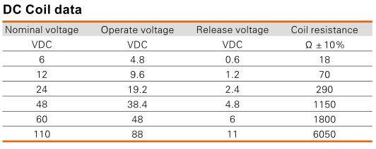 So for the 12VDC coil version, one needs at least 9.6V to be sure that the relay ‘operates’ and switches ON. To be certain it will release (or switch OFF) you need the coil voltage to be 1.2V or less. Unfortunately in this table we do not find a ‘hold’ voltage. After the relay has switched ON, it is possible to lower the voltage (and thus the power draw) significantly without triggering the relay to release or switch OFF. There are a couple of factors that influence the minimum hold voltage when using pulse width modulation.
- Input voltage before PWM has been applied
- Pulse width modulation frequency: obviously the frequency must not be too low, but also not higher than required to do the job.
- Duty cycle: this will directly influence the average voltage as seen by the coil.
- Power going through the relay: some inductive loads might have the effect of making the relay “stick”.
- The age of the relay: arguably the coil ages but also the spring which is used as counter balance.
This all depends on the type of the relay and thus must also be tuned and parametrized for the specific relay type.
A few tests on our setup, revealed it was possible to reliably reduce the duty cycle to
- 60% on an input-voltage-before-PWM of 11V, or a multi-meter-measured 6.7V as seen by the coil.
- 50% on an input-voltage-before-PWM of 12V, or a multi-meter-measured 5.8V as seen by the coil.
- 45% on an input-voltage-before-PWM of 13V, or a multi-meter-measured 5.5V as seen by the coil.
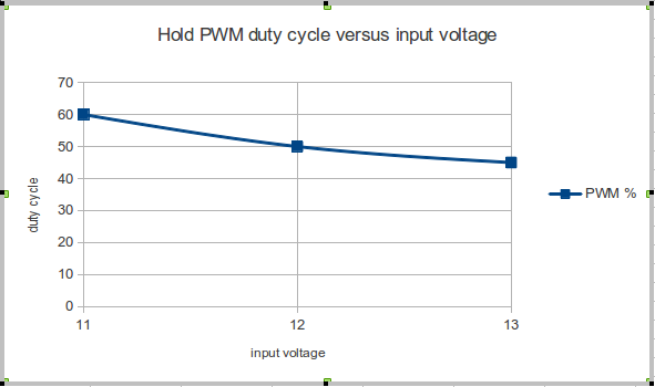
The PWM frequency during these tests was 100KHz.
(N.B. In this case the multi-meter is a bad tool for reading voltage as seen by the coil, but it gives a small indication…)
Further tests with more relay samples should provide more correct numbers, and then you would typically add a 10 to 15% increase as safety margin. Anyway, it seems that we can decrease the original 2W (worst case) power consumption, and save about 50%. Still, we will need to implement some logic on top of that to save even more energy. More on that in a next article.

Speak Your Mind