Introduction
In our project one source supplies power to two different loads and we need to control how much power goes to which load. To achieve this, we use an STM32F100 processor to PWM high-power mosfets. These mosfet channels do or do not conduct green energy to the different loads which are a battery (bank) and a dump load.

Suppose that we want to open each channel e.g. 30% of the PWM period (duty cycle = 30%). Then we want to investigate the impact of different PWM configurations: it is to be expected that results are different when open time of the channels do or do not overlap (read Ohm’s law for parallel circuits). In this article we explain how to configure different PWM configurations for 2-channel setups using ST ‘s Standard Peripheral Library. Real-world experiments with dump load and battery will be performed in the near future. If you are new to PWM then you might want to read this post.
PWM frequency is 100Hz in these examples which means the period is 10ms. We do not list gpio and basic timer configuration since ST’s library includes several examples. We have used TIM3 so no advanced features here (TIM1). ST’s manual can be found here. Chapter 13 ‘General-purpose timers (TIM2-TIM5)’ is relevant.
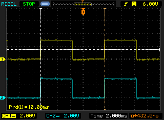
Both channels edge-aligned, same polarity
Nothing special here. Both channels have the same settings:
- polarity: active-high (TIM_OCPolarity_High),
- counter mode: upcounting (TIM_CounterMode_Up), and
- a duty cycle of 50%.
Both channels are active at the same time and thus Ohm’s law for parallel circuits applies.
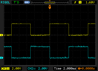
Both channels edge-aligned, different polarity
In this case each channel has a different polarity:
- yellow channel: active-high (TIM_OCPolarity_High), and
- cyan channel: active-low (TIM_OCPolarity_Low).
Warning: after configuration (and when duty cycle is 0%) the cyan channel has 3.3V so it might e.g. drive a FET.
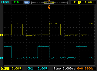
The first screenshot shows both channel with a duty cycle of 50%. In the second screenshot there is a gap because each channel only has 30% of the time 3.3 volts (i.e. duty cycles of 30% and 70%).
Both channels center-aligned, same polarity
While the previous examples were edge-aligned (upcounting or downcounting), this screenshot shows a center-aligned configuration. Configuration is as follows:
- both channels have same polarity: active-high,
- counter mode is up/down counting (TIM_CounterMode_CenterAligned3), and
- duty cycle is 70% and 30% respectively.
The result is that the cyan channel is ’embraced’ by the yellow channel.
Important: in order to get the same frequency as in edge-aligned mode, you need to divide the prescaler by two. This compensates the counting up and counting down (instead of counting up only).
To read more about different center-aligned counter modes (TIM_CounterMode_CenterAlignedx): see page 311 of CD00246267.pdf.
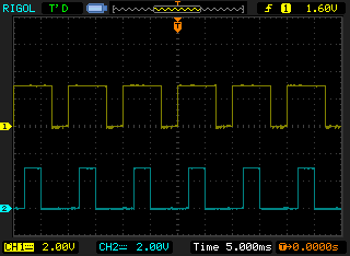
Both channels center-aligned, different polarity
Finally, in order to fully ‘separate’ channels (i.e. to have gaps between channel high), you need to have:
- different polarity (TIM_OCPolarity_High and TIM_OCPolarityLow),
- same counter mode (TIM_CounterMode_CenterAligned3).
This screenshot shows duty cycles of 70% and 30% (the same results is achievable by using upcounting with different polarity). Next screenshot shows duty cycles of 30% and 70% (which becomes 3.3V 30%). Here both channels are clearly separated by a gap.


Simple platform abstraction
In order to perform these experiments we extended our hardware abstraction layer as well.
A PWM output now includes an ‘alignment’ field. This enumeration field can be PWM_OUT_EDGE_ALIGNMENT or PWM_OUT_CENTER_ALIGNMENT.

Speak Your Mind