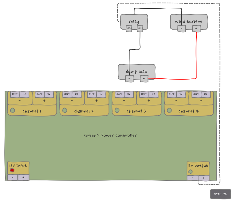
Wiring diagram: wind turbine to dump load
 In contrast to solar panels, a wind turbine can’t be disconnected in case it generates too much power. We need to brake it by attaching a load to it. However, wind power can’t always flow through the charge controller: high volts and/or amps might damage the internal circuitry of the charge controller. Therefore, an external but charge controller-driven circuit should brake the wind turbine.
With the Green4, this is done by controlling an external relay via a 12V output. By default (i.e. unpowered) the relay is in state NC (Normally Closed) and the circuit shown in the diagram is active: the dump load guarantees safe operation by burning wind energy and thus braking the wind turbine.
There are some difficulties though:
- when the wind turbine is in brake, it is a lot harder to start turning, and
- how does the charge controller know the current state of the wind turbine?
To some extend, both issues can be resolved by regularly pulling the relay to NO. The controller then is able to unload the turbine and sense wind power (each channel has both volts and amps sensors). There are some nice algorithms to discover here.
But what if generated power is higher than the charge controller’s specs? Without additional hardware (sensors), there is a danger to damage the charge controller when wind power comes in.
A simple solution is to install a voltage and/or current sensor in the shown circuit (e.g. this one, currently in development for production). The Green4 provides all I/Os to power and read input from such sensors.
Alternatively, one could use RPM by connecting the wind turbine to an frequency capture input. The controller can then relate RPM to wind power and do whatever is needed.
One more thing to mention: setting and keeping an external relay in NO also requires energy. But, because the 12V output is pwm-able, it is possible to considerably decrease power consumption by applying the technique described here.
Wiring diagram: wind turbine to batteries or dump load
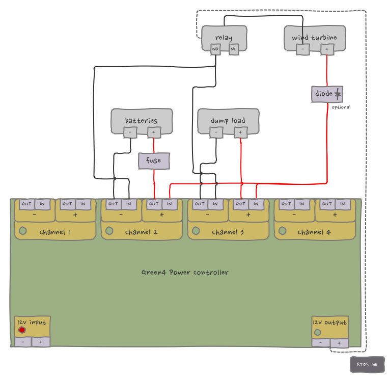 When the relay is driven to NO, it is possible to close two electrical circuits (again, all positives -red lines- are connected to each other):
- wind turbine to batteries (WT+ -> CH2+ -> BAT+ -> BAT- -> CH2- -> RELAYno -> WT-)
- wind turbine to dump load (WT+ -> CH3+ -> DUMPLOAD+ -> DUMPLOAD- -> CH3- -> RELAYno -> WT-)
By applying PWM on both channels CH2 and CH3, the controller should be able to safely and optimally charge batteries (more info here and here).
The wind turbine diode is only required when the wind turbine doesn’t have a bridge rectifier. You don’t want to power the wind turbine with your batteries…. in case the wind turbine generator is a DC motor.
Wiring diagram: all together
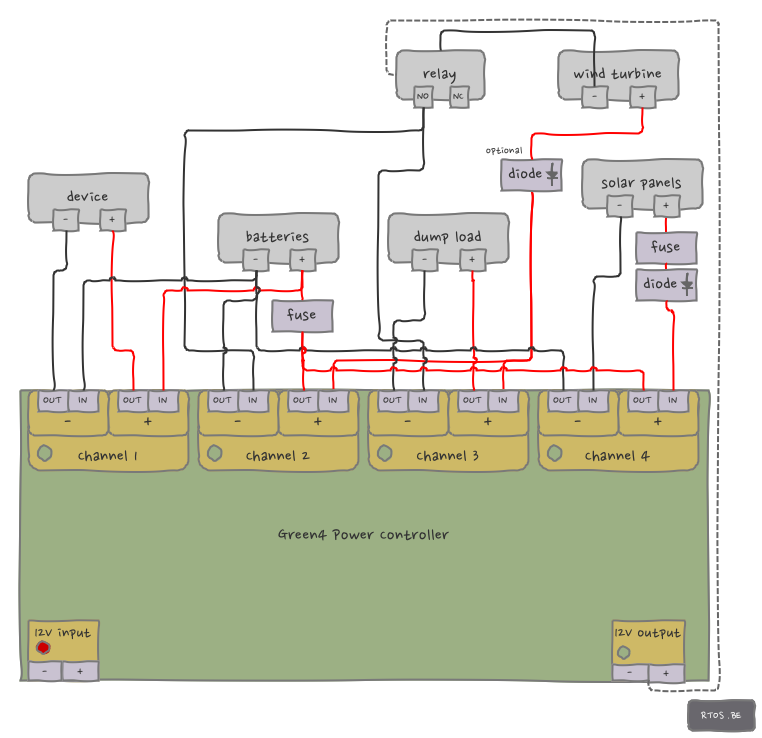
In this last diagram, all aforementioned use cases are combined into one complicated overview. The batteries play a dual role: on the one hand they deliver energy to an external device, on the other hand they are charged by wind and solar power sources. Although there are multiple power sources, only one source, namely the one that generates the highest voltage, is delivering energy.
All channels switch at the low-side (pluses are all connected). Because the electrical circuits mentioned in previous diagrams do not necessary share the same ground (reference), all Green4 channels must be able to switch independently from each other (i.e. without a common ground).

Speak Your Mind