Introduction
Instead of endlessly listing requirements and specifications, we prefer to demonstrate the architecture of our Green4 charge controller by means of wiring diagrams and other illustrations.
The Green4 is designed to be a versatile device that enables you to evaluate different charge controller architectures. Call it a charge controller emulator. There are several reasons for this intentional design choice:
- investigate pros and cons of different charge controller architectures
- Green4 can be sold as a generic power switching controller
- added value: it is hard to compete with existing cheap (Chinese) controllers
‘Added value’ because of flexible hardware and software:
- a set of fully-independent high-power switching channels which can be controlled by a programmable MCU,
- the Green4 will provide all software to program and/or script the device.
Convenience is important as well: we’ll do our very best to make life easier for the ‘Green4 engineer’.
The wiring diagrams only show one possible setup. In a later post, we’ll demonstrate an alternative.
Green4 overview
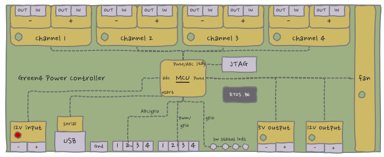
Let us start with a short list of hardware features:
- four 40A, 65V (2600W) pwm-able power channels to control current flow
- programmable MCU (serial and JTAG connection)
- pwm-able fan
- 5V and 12V pwm-able, low-power outputs (up to 0.5A)
- a generic set of inputs for digital input, analog input or input/frequency capture
- some status leds
- 12V board input (from e.g. a 12V battery)
We have made a diagram for every use-case:
- solar panels to batteries,
- batteries to (external) device,
- wind turbine to dump load,
- wind turbine to battery.
Finally, all use cases are combined into one (beast of a) diagram.
Wiring diagram: batteries to external device
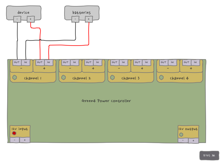 Green4 power channels always switch at the low-side i.e. between reference (ground, mass) and DEVICE-. Because in this case the batteries are the power supply, the reference is BATTERIES-. The positives (+) are always connected. So in order to close the electrical circuit, Channel1 has to connect CHANNEL1- IN with CHANNEL1- OUT.
A safety fuse between CHANNEL1+ out and DEVICE+ might be desirable.
Wiring diagram: solar panels to batteries
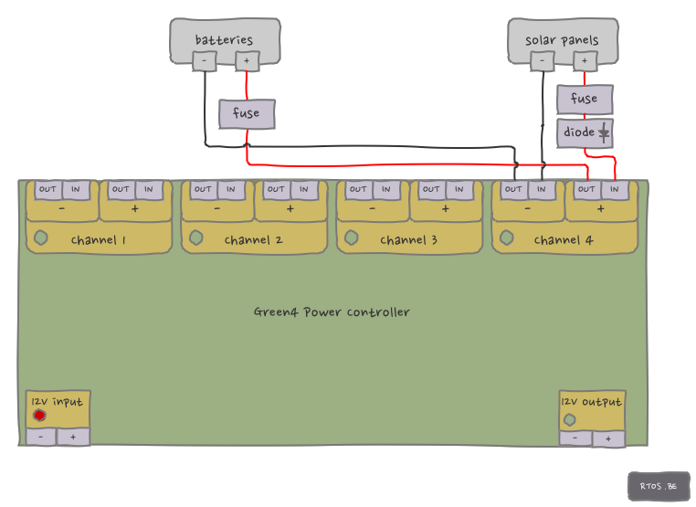 In contrast to previous diagram, batteries are consumer (i.e. load) and solar panels are producer (i.e. generator).
Again, all positives are connected (SOLARPANELS+, CHANNEL4+ IN and OUT, BATTERIES+) but we have added some protective features:
- diode: to guarantee current only flows in one direction (SP to BAT). The cost is a slight voltage drop.
- solar panels fuse: to protect the Green4 against overcurrent (in case solar panels produce >40A)
- batteries fuse: to protect the batteries against overcurrent (which can be very dangerous)
Channel4 opens and closes the circuit by switching CHANNEL4- IN and OUT.
Note that we can simply cut-off solar panels as they can only build a maximum ‘no-danger’ internal voltage. This is not true for wind turbine power generation (see later).

Speak Your Mind