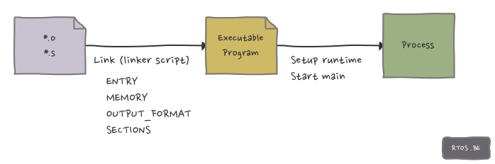
In part 1, we explained the main purpose of a linker: to put pieces of object code together into a single executable file. In this second and final part, we will discuss how we can control and adjust this process using linker scripts.
In short, linker scripts allow you to specify:
- input files: object files which are going to be linked together
- file formats: type of executable file, such as ELF, plain binary, …
- output file layout: how the executable file is organised internally
- addresses of sections
This article provides an overview of the most essential linker commands enabling you to grasp the majority of the linker scripts and to write one on your own.
A word on symbols
In the preceding article, the term symbol was mentioned a few times. As this concept is often used in linker scripts, now would be a good time to elaborate a bit on this matter.
When writing source code, we declare variables and functions to which we assign resp. values and instructions. The compiler stores the names of these variables and functions into a symbol table, often after having applied some sort of name mangling such as (in C) prepending a ‘_’. As we saw before, the symbol table not only holds the name (= symbol) of the variable or function, but also the location (i.e. address) of the symbol’s value in memory.
Declaring a symbol in a linker script, creates an entry in the symbol table. In below linker script, symbol a is declared and added to the symbol table:
a = 0xF000
However, no memory is reserved to hold any value. Any data that is assigned to this symbol, serves as the location of this symbol. In this case, symbol a gets memory address 0xF000.
As a consequence you cannot access the value of a linker script declared symbol. Hence, when referring to such a symbol in source code, you must always use the address of the symbol.
The following linker script and C code demonstrates this by copying the contents from ROM to RAM.
start_of_ROM   = .ROM;
end_of_ROM     = .ROM + sizeof (.ROM) - 1;
start_of_RAM = .RAM;
As we will see later on, .ROM and .RAM are examples of output sections. When the program is being loaded on an embedded device or by an operating system, the contents of these sections, code or data, is placed to the memory address to which these sections refer.
The actual copy operation in C:
extern char start_of_ROM, end_of_ROM, start_of_RAM;
memcpy (& start_of_RAM, & start_of_ROM,
        & end_of_ROM - & start_of_ROM);
Please note the use of the address operator &.
This kind of operation is not uncommon when initialising the C-runtime environment, albeit it is most likely implemented in assembler code.
Entry point
The entry point refers to the first instruction that will be executed when the program is loaded. This could be for example the main function or some startup routine which in itself invokes main. Commonly, the entry point is set using the ENTRY command.
This command takes a symbol name as argument, e.g. main.
ENTRY(symbol)
Other ways to specify the entry point are the ‘-e’ command-line option and assigning an address to the symbol start.
The default entry point for your toolchain, can be found out by executing ld –verbose. This command shows the default linker script for your toolchain. It most likely shows ENTRY(_start). This symbol is, as mentioned in part 1, provided by the C-runtime initialization file.
Memory
The MEMORY command describes the location and size of memory blocks on the target. This allows you to assign certain sections to particular memory regions. The syntax for the command looks like this:
MEMORY
{
    name [(attr)] : ORIGIN = origin, LENGTH = len
    ...
}
The attribute list may contain only the following characters:
- R: Read-only memory section
- W: Read/write section
- X: Executable section
- !: Inverts the meaning of the listed attributes
Using the ‘>’ operator you can instruct the linker to copy an output section in the SECTIONS command to a specific memory region. For example:
MEMORY
{
    rom (rx): ORIGIN = 0x1000, LENGTH = 0x100
}
SECTIONS
{
    .text:
    {
        *(.text)
    } >rom
}
The above script assigns the entire .text output section to the ROM memory region, located at address 0x1000.
Sections
As we saw earlier, an object file consists of multiple sections. The SECTIONS command is used to describe the memory layout of the output file, mapping the sections of the input files to the sections of the output file.
SECTIONS
{
    .data:
    {
         *(.data)
         _edata = .;
    }

    . = 0x2500;
    .text:
    {
         *(.text)
         *(.rodata)
         _etext = .;
    }
}
The above simple script shows an example use of the SECTIONS command. The command defines two output sections: .data and .text. All .data input sections from all input files (‘*’ as a wildcard) are copied into the .data output section. The location counter ‘ . ‘, which holds the current address and is incremented by the size of the output section, is assigned to a new symbol _edata. This symbol marks the end of the .data output section. The location counter is then set to address 0x2500. At this address starts .text output section into which all .text and .rodata input sections are copied. Again a new symbol _etext is defined, holding the address 0x2500 + sizeof(.text), which marks the end of the .text output section.
A final note on the location counter ‘ . ‘: it can only be used in the SECTIONS command and it is automatically initialized to 0 at the beginning of the command.
Output format
The output format defines the format of the executable, or the way in which it is internally organized. ‘objdump -i’ provides a list of the output formats that are supported by your tool chain. Some common formats are:
- binary: plain binary file format
- srec: hexadecimal ascii format
- ihex: intel hex text format
- elf32-i386: ELF format for 32 bit x86 architecture
- elf64-x86-64: ELF format for 64 bit x86 architecture
- elf32-littlearm: ELF format for 32 bit little endian ARM architecture
- elf32-bigarm: ELF format for 32 bit big endian ARM architecture
The output format is specified by means of the OUTPUT_FORMAT command of which two variants exist:
OUTPUT_FORMAT(format)
This variant is equivalent to ‘–oformat format’ on the command line.
OUTPUT_FORMAT(default_format, big-endian_format,
              little-endian_format)
When setting the desired endianness using ‘-EB’ or ‘-EL’ at the command line for resp. big and little endianness, this variant allows to select the proper format depending on the endianness. If neither command-line option is present, the default format is selected.

Speak Your Mind