Each battery(bank) has properties such as
- voltage and
- maximum load amperage and
It also behaves differently (in our context of energy harvesting) depending on its
- state of charge (empty, half, full).
To charge a battery efficiently and safely the (average) voltage and (average) load current must be measured, filtered and checked continuously.
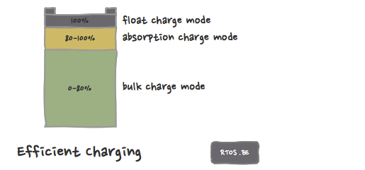
First thing a charge controller must do on initial start-up, is determine the nominal battery bank voltage: Is it a 12V, 24V or 48V battery bank? Then, we can have some rudimentary boundaries for the charge modes to work on. Three different charge modes are differentiated:
- Bulk,
- Absorption, and
- Float or trickle charge mode.
Maximum charge amperage
During bulk mode, the charge controller is allowed to dump maximum allowed charge amperage into the batteries. Battery voltage is mapped to the load state of the battery, since the higher the load state, the higher the battery voltage. Actual voltage levels differ from battery to battery type.
Bulk mode is usually defined by an arbitrary up-to-80% load state of the batteries. In absorption state, the load current must be gradually diminished until the float level current is reached.
When in bulk charge mode, the energy harvester should charge the batteries in the most efficient way up to – and thus limited to – maximum charge current of the batteries.
Limited charge amperage
When in absorption and float charge mode, the charge Amp limit is further decreased. Hence, as stated earlier, current and voltage levels should be closely monitored.
The boundaries between the different charge modes in not always clear cut. A hysteresis is applied to the voltage boundary values.
- The “SetBulkVoltage” is the voltage value that will trigger absorption mode when the battery voltage raises above it.
- The “SetAbsorptionVoltage” is the voltage that will trigger float or trickle mode when the battery voltage raises above it. However, we only move from absorption to bulk mode when battery voltage decreases below the SetBulkVoltage minus a hysteresis value. This must ensure that we do not “bounce” between the different modes.
- The “SetFloatVoltage” is the voltage that will trigger a charge STOP, hence the same system as described before is used between absorption and float mode. No more current is flowing from source to batteries, but it is possible that current flows from batteries to dump load or normal load as we will see later. Again, we will only move from STOP to float charge mode when battery voltage decreases below SetFloatVoltage minus a hysteresis value.
If maximum charge amperage in bulk charge mode is nSetBulkAmps, and maximum charge amperage in float charge mode is nSetFloatAmps, with nSetBulkAmps > nSetFloatAmps of course, then the maximum charge amperage in absorption mode is determined by a linear equation.
Amp Difference = nSetBulkAmps – nSetFloatAmps;
Voltage Difference = nSetAbsorptionVoltage – nSetBulkVoltage;
Current Voltage Delta = nSetAbsorptionVoltage – nCurrentVoltage;
Amp supplement = (Current Voltage Delta / Voltage Difference) * Amp Difference;
Applied maximum Amperage charge limit is then
Limited Charge Amperage = nSetFloatAmps + Amp supplement.
The formula can be confusing because nSetAbsorptionVoltage determines the boundary for the change between Absorption and Float charge mode. Also, one must take care that during calculation the voltage ratio (Current Voltage Delta / Voltage Difference) cannot become negative and cannot become higher than 1: The fraction value must be limited between 0 and 1.
So, this is our simple charge strategy, but this can get in conflict with the (wind turbine) control strategy.
The control strategy
The wind turbine delivers power to the energy harvester. Without load, the generator produces an open voltage which is more or less linear with the RPM at which the blades rotate. Over-speeding will potentially kill the turbine, and over-voltage is dangerous to the energy harvester itself. The turbine needs a load to slow it down and keep the voltage within safe system levels. This load can be the battery, a dump load or a generator short-circuit. Although the latter is usually not a good idea because the generator might burn-out after which the turbine risks to be completely out of control. When the battery bank is full (or the generated energy is more than the allowed battery bank charge amperage), the (excess) energy needs to be diverted to the dump load. Some systems also keep the battery connected to the dump load at that time. Then, when dumping excess energy and braking the turbine, also the battery bank will be discharged slightly. This is not a bad thing, because afterwards the battery bank might have room again to absorb generated energy.
A low safety boundary voltage is defined, at which the controller will start to brake (1%) the wind turbine by diverting energy to the dump load. The high safety boundary voltage will trigger a 100% brake. Measured voltage levels between low and high boundaries will translate into brake percentages between 1 and 100% again using a linear equation taking the voltage ratio into account.
Not only voltage but also generated current must be monitored. If the safe electrical current boundaries of the system are reached (i.e. the alarm safety boundary), other measures must be taken: This might trigger an external high amperage capable relay switch, which will disconnect the turbine generator from the harvester, but at the same time, connect it directly to the dump load. Only when the turbine is under control once more, the harvester can be connected again.
It is clear that the implementation of such a control system allows for more advanced, smoother and more fine-grained control of the turbine: There is more than only a 0 (no brake) and 100% (full brake) state available.
Electro-mechanical power harvesting optimization
Furthermore, when charging the battery, it is not necessary nor mandatory to keep the generator 100% of the time connected to the battery. If, when in bulk or absorption charge mode, one connects the generator to the battery bank continuously, the state of charge and the battery bank voltage determines the work regime of the turbine. Depending on the wind, it might be better to let the (turbine) generator run at a higher RPM (and thus higher generated voltage) by partially (<100% duty cycle) disconnecting it from the batteries. When trying to optimize the mechanical to electrical energy conversion that way, one needs to continuously evaluate the generated power with regard to the applied duty cycle.
Safety
Important to note is that, should mosfets fail, they will conduct 100% of the time, effectively connecting the generator to the battery bank 100% of the time. The other (dump load) mosfet will then need to keep things under control by diverting excess (generator and battery) energy to the dump load. In the unlikely event that also the dump load mosfet fails, the entire battery bank energy will gradually be dumped to the dump load. This is usually devastating for the bank, but at least the wind turbine will still be safe and under control because of the external relay in our design.

Speak Your Mind