Introduction
The core of our charge controller (PMD2) is essentially two switchable mosfet channels: one channel to load a battery (bank) and another channel to divert abundant energy to a dump load. Both channels can be switched on/off by software controlled PWM, and by configuring different PWM duty cycle ratios, we should be able:
- to avoid battery overcharging and
- to charge efficiently.

The figure illustrates this concept: by playing with the PWM duty cycle we can control how much energy flows to which device (note: the total doesn’t necessarily have to be 100%).
Experiment 1: one channel, low-side switching
But first things first: in our first experiment we restrict ourselves to just one channel. We are going to charge a battery the hard way i.e. dump energy in the battery via a PWM-driven mosfet without making use of “fancy” software control algorithms (these algorithms are necessary for efficient and safe (!) charging but we will elaborate on this in later articles).
So here is our setup.
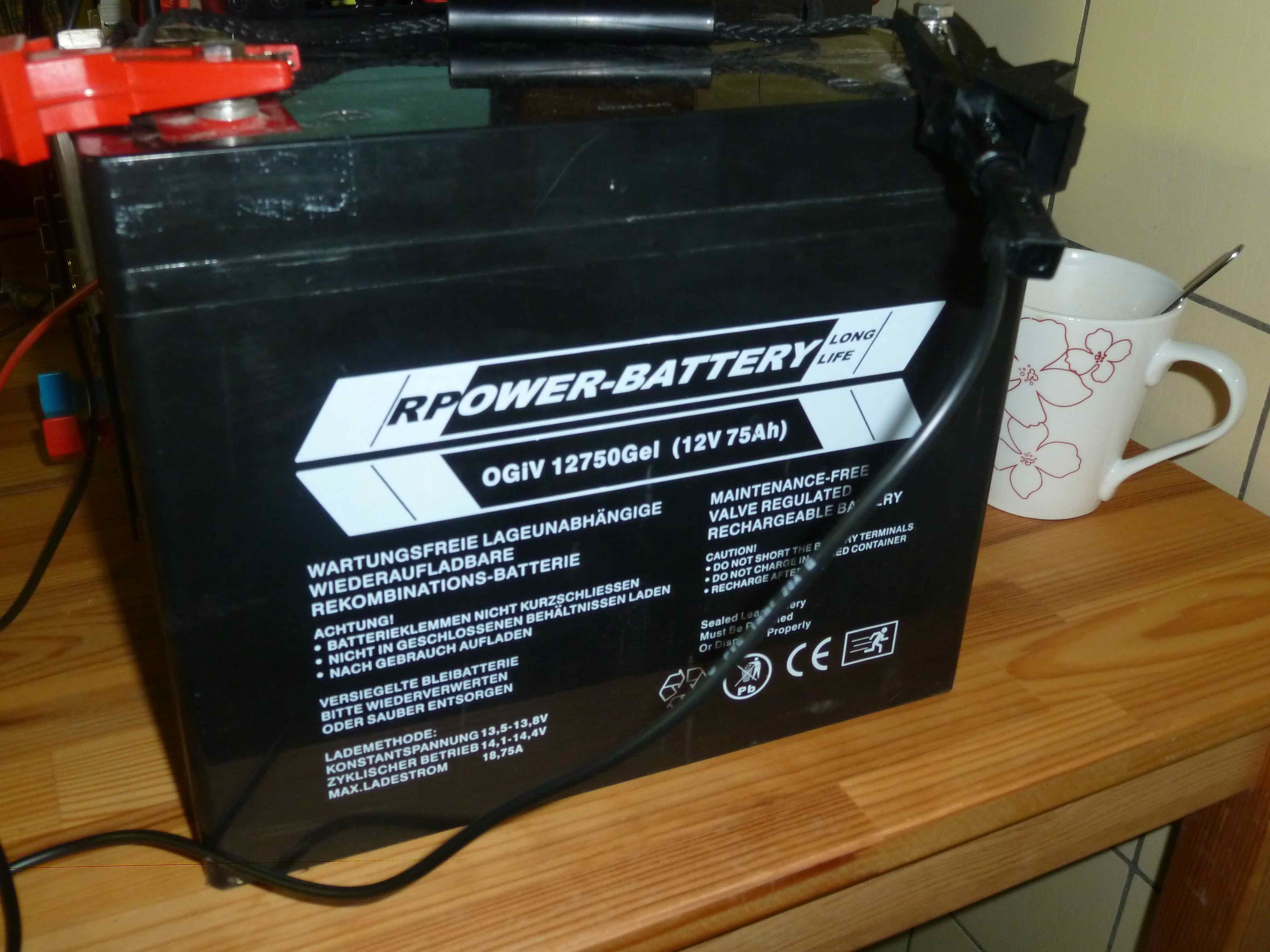
A 12V, 75Ah deep-cycle battery (and a cup of coffee to survive late evening debugging):
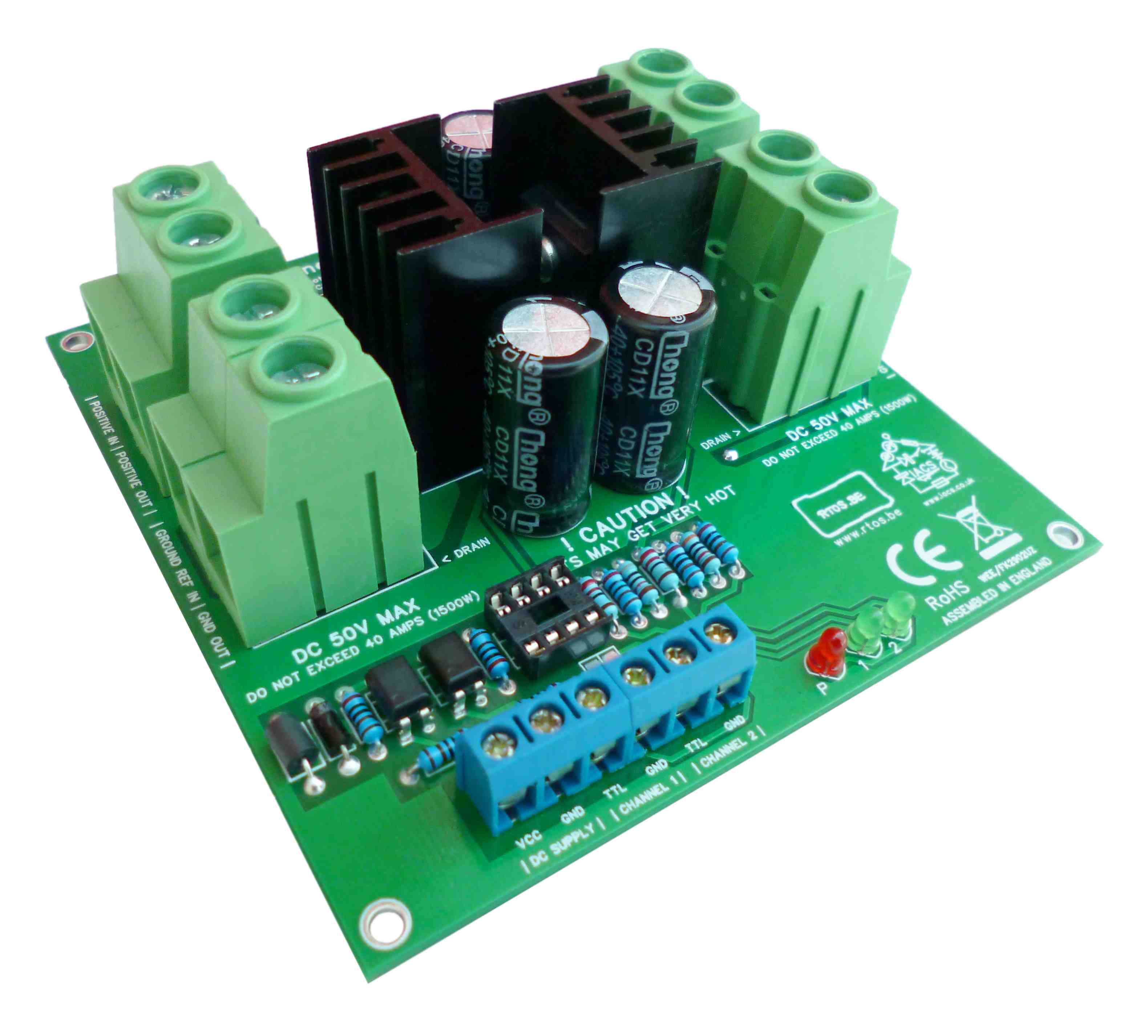
Our low-side switching board “energy 2 switch”. This board has been developed and tested by IACS and RTOS, and will be commercialized in the near future.
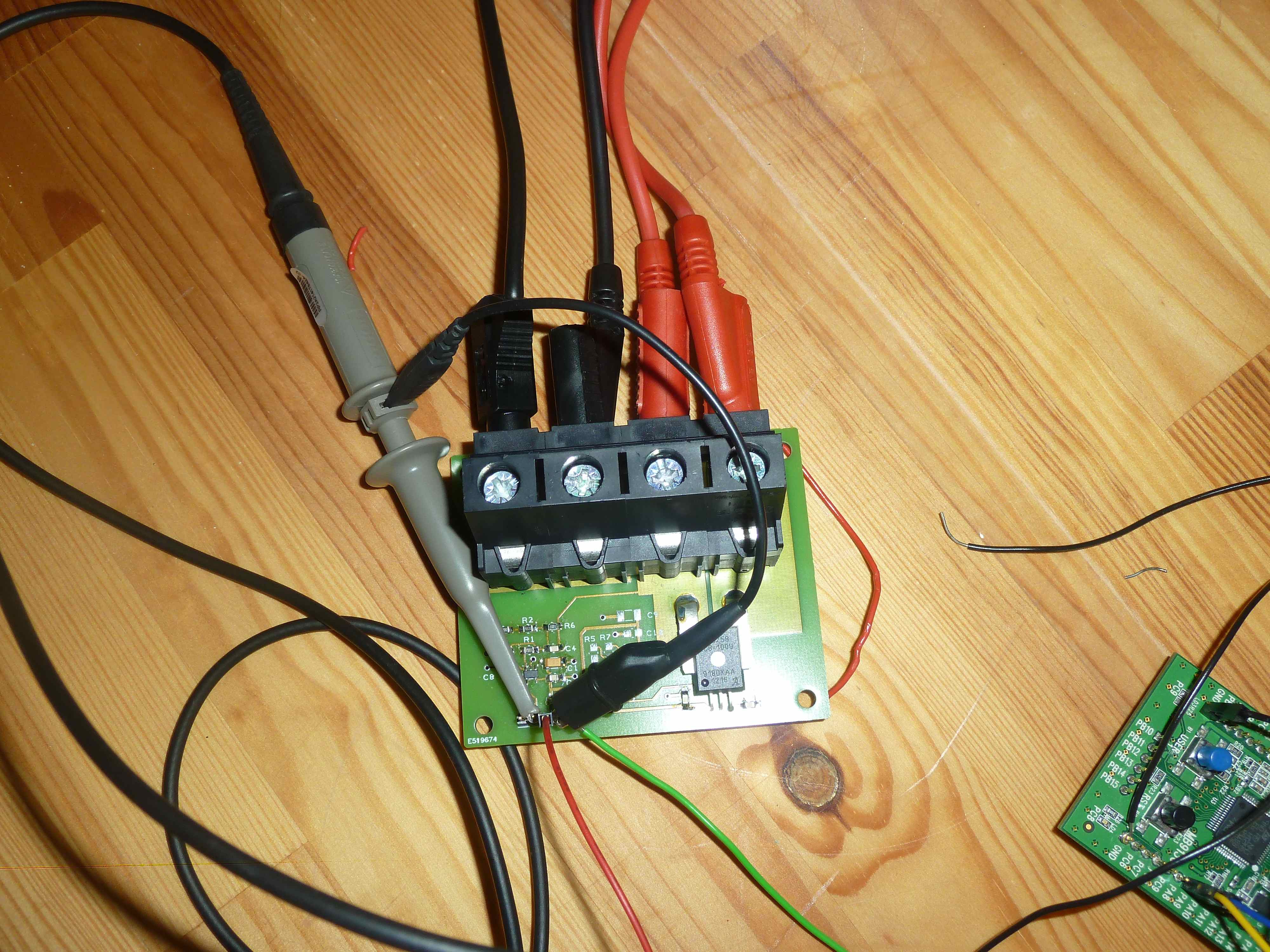
Our sensor board that enables us to read battery volts and amps:
Of course, there is a PSU as well to supply energy (no need to show a picture).
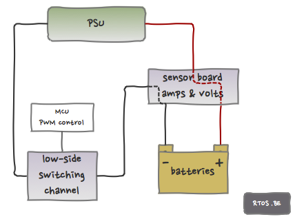
All these devices are connected to each other. Here is the connection diagram (read this post to understand low-side switching wiring; essentially, switching is done by connecting the ‘-‘ of the load to the ‘-‘ reference).
Before the test, the battery’s voltage was 11.77V. In order to be able to charge the battery, the voltage of the power supply must be higher of course. For convenience, we take e.g. 16V.
By varying the duty cycle of the PWM, we should be able to control how much power goes to the battery. Here are the results (PWM frequency = 100Hz):
100% DutyCycle => 16A (shown at display of PSU)
75% DC: 14A->11.8A (~12A – perfect setup)
50% DC: 12A->9.0A (~8A)
25% DC: 9A->6.3A (~4A)
The measured amps decrease until it more or less stabilizes after a few tens of seconds. After this short test, the battery’s voltage has increased to 12.2V. We have been charging batteries here!!!
Another interesting thing to show is the scope output of the sensor board (amps and volts). The amps output shows – as expected – a rather clean block wave.
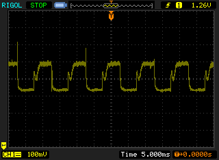
The volts output shows a ‘peaky’ block wave (the average is correct though). We have been told that this is normal for a capacitive load, although it is hard to explain. Maybe someone of our readers can help us out?

Upcoming
Next in this series are charging a battery via high-side mosfet switching and after that, we will investigate two-channel setups (to dumpload and battery).

Thanks for giving such a great information. Good work, keep on posting.