Introduction
The goal of each system is to perform its intended function. Easier said than done in an imperfect world, and that is what this article is about: how to design a system in such a way that the probability of hazard exposure is acceptably low. The presented techniques are well-known in the world of safety-critical systems (functional safety in automotive, avionics, railways…), for demonstration purposes though, we apply these techniques on one aspect with regard to the system safety of our energy harvester: how to protect the charge controller internals against an input current which is higher than the spec’d 40A? Analyzing (and solving) this system safety requirement requires a system-level view because we don’t know yet whether the solution (if we need one?!) will be in mechanics, hardware or software. The focus here is to analyze the problem so we can create a good system design (if we don’t do this now it might be too late…).
Fail-safe state
Before we start the analysis we need to identify the fail-safe state which is the state you want to revert to when something goes wrong. The fail-safe state of the charge controller is not to accept any power which means that:
– the power of the wind turbine is diverted to the dump load, and
– the solar panels are disconnected.
Hazard analysis
Now we can start with the hazard analysis. Given our two green power inputs, there are (at least) three hazards that can destroy the internal hardware of the charge controller:
- solar power (current) > 40A,
- wind power > 40A,
- combined power > 40A.
In all 3 cases the level of risk is very severe as they will probably ‘burn’ the charge controller within a short time frame (so the tolerance time for a fault is very short but unknown).
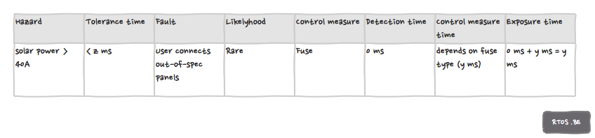
Hazard: solar power > 40A
This is the easiest hazard to analyze. The figure depicts our hazard analysis: a (correct) fuse will do. Note that the exposure time (detection time + control measure time) should be less than the tolerance time.
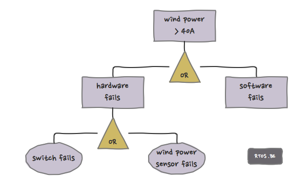
Hazard: wind power > 40A
In this case we follow a top-down approach which is called fault tree analysis. Without safety measures our fault tree looks like this:
For software, we take the easy way out and assume that there’s a (hopefully!) small probability that buggy code exposes a hazard. Can we take any measures? E.g. could a watchdog be of any help? Sure, if the software fails and if the watchdog is triggered then the ECU will reset and the outputs will reset to ‘input’. We then hope the switch (which is controlled by a gpio output) will return to its default state which is ‘divert energy to dump load’. So to some extend we mitigated the effect of having bad software (however there is still the issue of detection time). In next figure, you can see this depicted as an ‘AND’ gate: the probabilities of failures are multiplied with each other (instead of added in case of an ‘OR’ gate). ‘AND’ gates is what we need here!
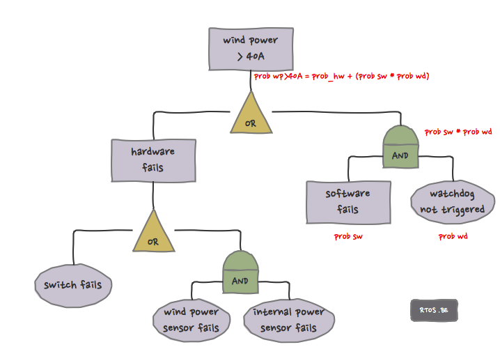
Similarly, the effect of having a faulty or broken-down wind power sensor is mitigated by the internal power sensor (see logic hw design). Although the internal sensor is spec’d for the internal current range (up to 40-50A), it can still be used to detect an overload on which the software can turn off the switch. A (probabilistic) event tree (bottom-up approach) is another way to visualize this:
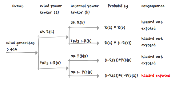
And again, the goal is to increase the probability of ‘no hazard exposure’.
This brings us to the following table:
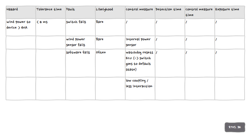
Most cells are still blank. This is perfectly fine because hazard analysis is an iterative task as well. At least we have something!
There are tons of other faults e.g. cables incorrectly attached, bad PCB connections etc. but these are beyond the scope of this article.
Hazard: solar and wind power > 40A to the device
Because this hazard is very similar to the previous one, we leave the details.
Conclusion
The aforementioned techniques help us reason about unwanted situations. We at least learned the following things:
- the importance of the fuse to protect the charge controller from too high solar power,
- the watchdog can help us to revert to the fail-safe state,
- guarding the system safety requires processing both wind and internal sensors.
One final note: next to Fault Tree Analysis and Event Tree Analysis, there is the Failure Mode and Effect Analysis (FMEA) which we didn’t discuss here.

Speak Your Mind