Introduction
One of the goals of iteration 1 of the energy harvester project is to extend our software platform with drivers for measuring (gpio in, adc), controlling (gpio out, pwm) and debugging (uart). In this article our focus is set on the ADC driver (we already introduced the Analog-to-Digital-Converter here).
It is hard (not to say impossible) to define a generic and workable ADC interface which supports all possible ADC features. For example, the ADC peripheral of the STM32 microcontrollers provides: single- or multi-channel, single, continuous or injected conversion modes; in addition, various dual modes exist such as regular, fast interleaved, slow interleaved, alternate trigger and combined regular/inject simultaneous mode. Wow :-).
The application note of ST can be found here. Of course, this complexity is the consequence of the variety of possible applications which run on these kind of microcontrollers.
ADC interface
For our charge controller application we only need to be able to continuously scan a set of channels. The microcontroller provides 18 channels to measure 16 external + 2 internal sources. That should be enough for our app. The channel resolution is 12-bit which means for an input range between 0 and 3300 mV, the Voltage resolution is 3300mV/4096 or 0.81mV.
In order to define the interface, let us start with some enum’s:
/*! The list of available ADC's */

enum ADC {

        ADC_1 = 0,

};


/*! Adc modes. */

enum adc_mode {

        scan_continuous

};


/*! Adc sample times (can be defined for each channel). */

enum sample_time {

        sample_time_1cycles5 = 0,

        sample_time_7cycles5,

        sample_time_13cycles5,

        sample_time_28cycles5,

        sample_time_41cycles5,

        sample_time_55cycles5,

        sample_time_71cycles5,

        sample_time_239cycles5,

};
Then, an ADC channel can be defined as follows:
typedef struct adc_channel {

        PIN pin; /* you can use pin e.g. PA3 or channel e.g. ADC1_IN3 */

        enum sample_time sample_time;

} adc_channel_t;

#define ADC_CHANNEL_INVALID {.pin = PIN_INVALID} /* last entry in channel array */
Note the ADC_CHANNEL_INVALID macro. This macro must be used as the last entry of an array of channels as is shown in next code snippet (an alternative interface would be to use an array of pointers to channels; in that case, the last entry would be NULL; different solutions with different advantages and disadvantages):
static const adc_channel_t adc_channels[] = {

        { PC0, sample_time_55cycles5 },

        { PC1, sample_time_55cycles5 },

        { PC2, sample_time_55cycles5 },

        { PC3, sample_time_55cycles5 },

        { PC4, sample_time_55cycles5 },

        ADC_CHANNEL_INVALID

};
Finally, here are the functions:
/*! Initialize an adc with a mode and an array of channels. */

BOOLEAN adc_init(enum ADC adc, enum adc_mode mode, const adc_channel_t* channels);


/*! Start sampling. */

BOOLEAN adc_start(enum ADC adc);


/*! Get the sample of a channel. */

ADC_SAMPLE adc_get_sample(enum ADC adc, const adc_channel_t* p_ch);


/*! Get a collection of samples. */

void adc_get_samples(enum ADC adc, IN const adc_channel_t* channels, OUT ADC_SAMPLE* samples);
The full api can be found here.
This is a simple example of the API at work, using the aforementioned adc_channels array:
        ADC_SAMPLE samples[5];

        adc_get_samples(ADC_1,adc_channels,samples);

        ...
ADC driver implementation: DMA
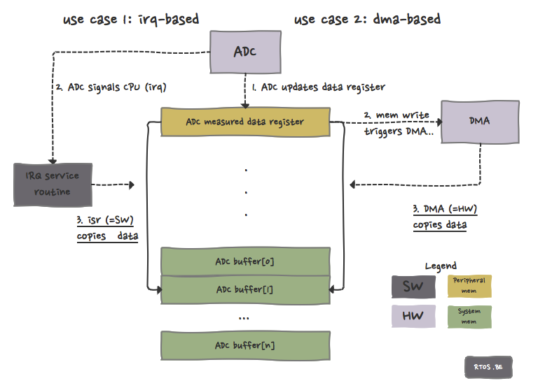
Because the driver continuously scans all channels, it would be a system load killer if we implemented the driver in a straightforward way (see Figure, use case 1):
- ADC writes a new sample in its data register and
- triggers interrupt
- interrupt handler copies the sample from the register (peripheral memory) to the buffer (system memory)
- and so on… (do this for each channel and then restart the whole process)
This would mean that the cpu is (heavily) loaded because of the copying of data from peripheral memory to system memory. It would be nice if we could avoid this overhead. And we can do this by using Direct Memory Access (DMA). See Figure, use case 2: no software (~ cpu time) is involved in the copying process, everything is done by hardware. Yes!
So our driver uses DMA to write the results in a buffer. This buffer is then accessible via the aforementioned API.
Testing the driver
We tested the driver with both the Olimex STM32-p103 and STM32 Value Line Discovery development boards. To make the testing more fun we used our LED library and implemented the following:
- LED is off when the input voltage < 1V,
- LED blinks slowly when the input voltage is between 1V and 2V,
- LED blinks faster when the input voltage is between 2V and 3V,
- LED is always on when input voltage > 3V.
Watch the video if you search for proof! You can see the input voltage through the wiring :-).
Check your reference voltage!
When testing the ADC driver, we noticed that in some cases the ADC measurements where significantly lower than the input voltage (up to 200-300mV). The reason was that the MCU voltage (which is used as a reference by the ADC peripheral) was not 3.3V but lower! This resulted in incorrect ADC samples.
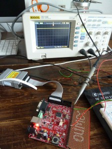
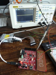
The Figure left shows the Olimex STM32-P103 without OpenOCD JTAG connected while the Figure on the right side shows the situation when the JTAG is connected. On the scope, you can see a difference of 1V! Wow again :-).

Speak Your Mind