Introduction
 As embedded software engineers, we might not have an in-depth understanding of all electronic charge movements through semiconductor circuits, but at least we’re able to reason about hardware design at a concept level. In a previous post we introduced the energy harvester’s Power Management concept. We now elaborate on this and propose our initial logic hardware design. This design is – of course – not final yet and will evolve iteration after iteration. The goal is to actually prototype this design (or a successor) by using COTS components if feasible. We’ll leave the nasty hardware details to a specialist hardware designer.
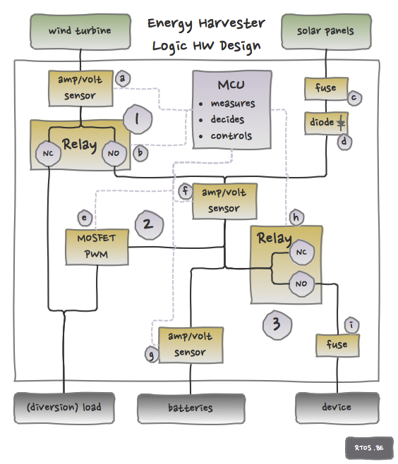
The Figure represents the simplest standard PWM-based charge controller architecture. It has 4 parts: the MCU, Power Management Decision 1 (PMD1), PMD2 and PMD3. Note that the grounds of all components are connected although this is not drawn on the schematic below.
MCU
The software-driven MCU is the brain of the charge controller. Its goal is to optimally use the available wind and solar energy. In order to achieve this the MCU receives information from the PMD’s by means of sensors and controls components via actuators. How the MCU makes its control decisions is part of the software discipline.
Power management decision 1
Decision concept: send the wind turbine power to the load or to the batteries?
Rationale:
- always accept wind power in order to protect wind turbine
- allow a wide range of wind turbines (also the bigger ones) but protect charge controller internal electronics
- get rid of wind power when it’s useless (e.g. full battery pack, lots of solar power…)
Sensors and actuators:
- Amp/volt sensor, see (a) in Figure: enables the MCU to measure the incoming wind power
- ‘Gate keeper’ relay (b): enables the MCU to control the destination of the wind power. For safety reasons the power is diverted to the dump load by default.
Remarks, difficulties and risks:
- high input power
- dump load must be spec’d in accordance with wind turbine
- disconnecting the relay might be difficult (see this post)
Power management decision 2
Decision concept: send power to batteries or to dump load?
Rationale:
- charge batteries in an optimal way
- protect the batteries (e.g. against over-charge and over-current)
- harvest the green power in an optimal way (e.g. MPPT, although it is not implemented in this design yet)
Sensor and actuators:
- Fuse (c): the device cannot handle more then the spec’d solar energy, otherwise this fuse will blow when an over-current situation occurs.
- Diode(s) (d): the solar panel connection is protected against reverse current by diodes (which prevent the wind power and battery power from flowing to the solar panels). When using a DC motor as wind turbine, an additional diode would certainly be required.
- Mosfet PWM (e): the mosfet PWM allows the MCU to divert power to the dump load when over-current or over-charge situations with regard to the battery occur. This is a simplification but it means that a duty cycle of 100% dumps all the power in the diversion load, a duty cycle of 0% dumps all the power in the battery bank.
- Amp/volt sensor (f): measure the available wind/solar power
Remarks, difficulties and risks:
- when dumping energy to the dump load, the battery bank is still/also connected (to the dump load) which does not matter is case of excess energy (this is the standard scheme of “diversion” controlling)
- although the charge controller ‘combines’ the power from both input, the highest voltage input ‘wins’. So, typically and most of the time, only one input provides power to the device which makes MPPT more applicable. There are moments when voltages of both sources are equal. In that case, power is drawn from both.
Power management decision 3
Decision concept: connect the external device? send wind/solar power or battery power to an external device?
Rationale:
- well… you need to do something with the available power
- protect the batteries against depletion
- protect the charge controller internal circuitry
- save enough battery power to supply the charge controller itself
Sensors and actuators:
- Amp/volt sensor (f): measure the available wind/solar power
- Amp/volt sensor (g): measure the battery power
- Relay (h): connect or disconnect the external device. If the voltage of the battery bank is sufficient, the output will be enabled. If insufficient, the output will be cut off.
- Fuse (i): protect the charge controller (and batteries) against too high external load
Remarks, difficulties and risks:
- the output voltage might be unstable, especially when relays are toggled or PWM ratio is changing, but it also depends on the state of charge of the batteries.


Speak Your Mind