Introduction
The dump load (already introduced here) is used to burn the excess energy of our battery charger. The excess is typically generated by the wind turbine in windy conditions. In contrast with solar energy, the battery charger must accept wind energy in order to protect the wind turbine. For that reason the dump load (how much power it can dissipate into heat) must be chosen in accordance with the (size of) the wind turbine.
This experiment improves our domain knowledge about dump loads and wiring, and is part of “Power Management Decision 1” (see system architecture). It results in some requirements.
Dump load
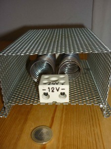
For this little experiment we use a dump load which we bought on ebay (GBP 29.50). It consists of 2 dump load elements and supports a 12V or a 24V system.
According to the ‘spec’ it is able to dump 70A at about 14.5V (or 1015W) in the 12V setup (2 elements in parallel), or 29Vx35A (or 1015W) in the 24V setup (2 elements in series).
This dump load is not industrial quality.
Experiment
The experiment is basic (i.e. “as basic as it gets”): find out the resistance of the dump load. There are at least two ways to do this:
- use a multimeter, or
- use Ohm’s law (R=V/I) to derive the dump load’s resistance. This allows us to test our new (strong) power supply and learn about safe wiring as well.
We did both.
Although a relatively small wind turbine can already generate up to 100 Amps or more, our power supply is ‘only’ spec’d 30V/40A. Good enough.
On this website one can find the guidelines for choosing the correct wire. The guidelines are (very) conservative as you can read in this quote:
The Maximum Amps for Power Transmission uses the 700 circular mils per amp rule, which is very very conservative. The Maximum Amps for Chassis Wiring is also a conservative rating, but is meant for wiring in air, and not in a bundle.
But also:
For short lengths of wire, such as is used in battery packs you should trade off the resistance and load with size, weight, and flexibility.
And that’s exactly what we did: for this experiment we choose a 6mm^2 copper wire. With a diameter of 2.76mm (between 9 and 10 AWG gauche) this wire is still quite flexible. Following the guidelines, the load carrying capacities of this wire are 55A-64A for chassis wiring and 15-19A for power transmission. As these numbers are conservative we can regard our relatively short 6mm^2 wires as safe for our little experiment.
The colours of the wires might be a little misleading as they are pragmatically chosen (in the local shop all other colours were sold out for this type of wire 🙂 ). Read here about colour standardization.
Because the wires are very short, we can ignore their resistance.
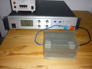
12V setup (the 2 wired ‘coils’ in parallel)
Picture of the 12V setup (but only one dump load element is connected), burning energy at +- 20A:
Resistance measured with multimeter: 1.1 Ohm
Resistance derived from Ohm’s law:
- current limitation 40A: 11.9V/31.6A = 0,38 Ohm
- current limitation 30A: 11.4V/29.9A = 0.38 Ohm
- current limitation 20A: 7.4V/19.5A = 0.38 Ohm
- current limitation 10A: 1V/2.7A = 0.37 Ohm
And yes, the dump load is really getting hot… The wires and metal protection of the dump load didn’t.
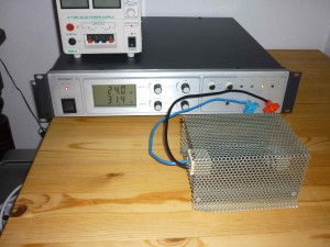
24V setup (the 2 wired ‘coils’ in series)
Picture 24V setup, burning energy at >30A:
Resistance measured with multimeter: 1.4 Ohm
Resistance derived from Ohm’s law:
- current limitation 40A: 24V/32.1A = 0,75 Ohm
- current limitation 30A: 22.3V/29.9A = 0,75 Ohm
- current limitation 20A: 14.5V/19.6A = 0,74 Ohm
- current limitation 10A: 6.9V/9.3A = 0,74 Ohm
Conclusions
- The resistance of one dump wire (coil) is +- 0.38 Ohm.
- Our multimeter is not very reliable to measure the resistance at that resolution.
- In this experiment the diameter of the wire (2.76mm) finds a good balance between load carrying capabilities and handling (flexibility). The wires didn’t get hot.
Requirements
- The wiring in the charge controller shall be able to resist the specified amps.
- If a dump load is used to burn the excess energy then it shall be specified in accordance with the wind turbine.
- If a dump load is used to burn the excess energy then it shall have a resistance lower than 1 Ohm per 1000W.


Note that resistance can change when the element is hotter. Therefore Real wattage can change. I also have this same dump load in my 1kW wind turbine but havent yet tested it. It tried little test putting 12V car battery to power it and its getting very hot.. glows red. Im scared if that burn my whole house lol.
Hi wind man,
we have tried to measure the temperature of a red-glowing dump load with an infrared thermometer (e.g. see here for a picture) but the thermometer became out-of-range. This means more than 420 °C :-). When the color changes from red-glowing to white-glowing, your dump load is melting away…